

Bond beam rebar positioner
a technology of rebar positioner and bond beam, which is applied in the direction of building reinforcements, construction, building components, etc., can solve the problems of degrading the structural performance of the bond beam
- Summary
- Abstract
- Description
- Claims
- Application Information
AI Technical Summary
Benefits of technology
Problems solved by technology
Method used
Image

Examples
first embodiment
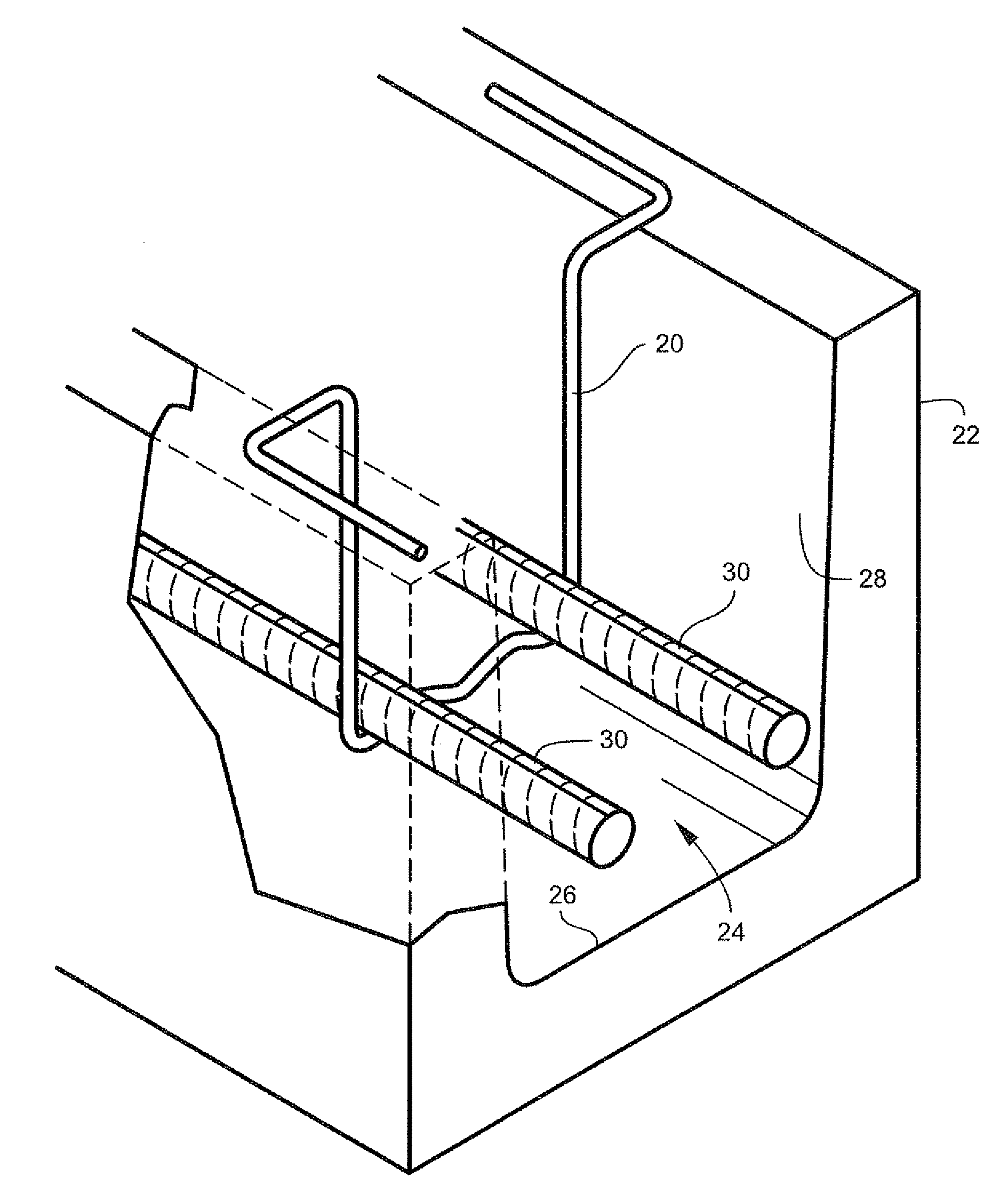
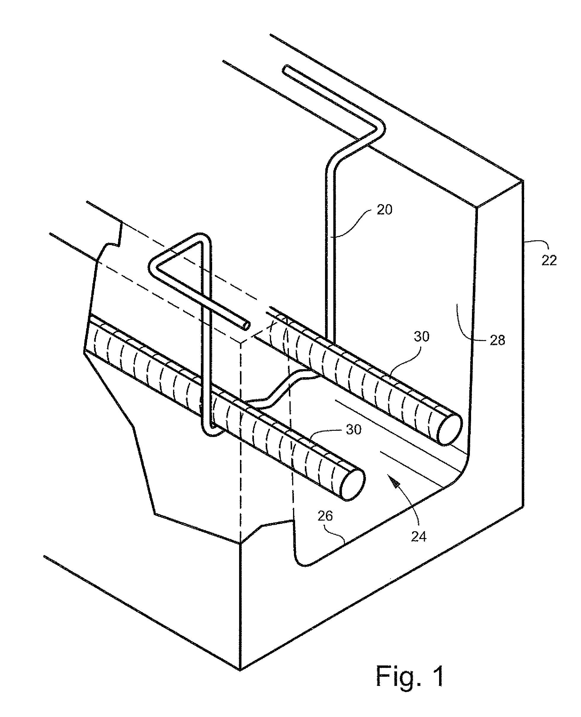
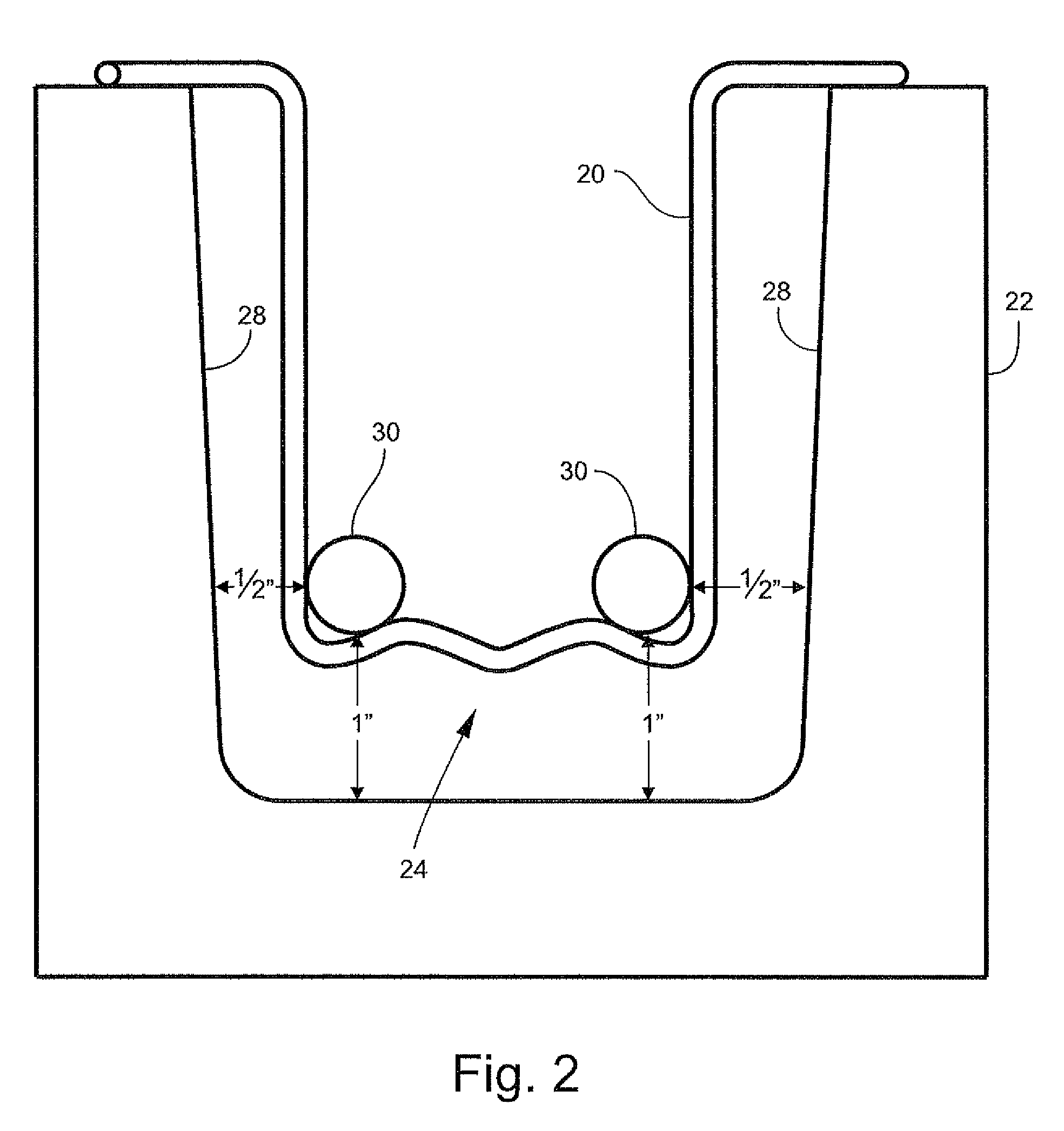
[0031]Referring to FIGS. 1-9, a first embodiment of a rebar positioner is shown generally at reference numeral 20. Referring specifically to FIGS. 1-2, rebar positioner 20, in the exemplary application shown, functions to properly position at least one length of rebar within a channel of a bond beam such that the rebar is properly positioned with respect to the bottom and sides of the channel, and with respect to additional lengths or rebar, during bond beam construction.
[0032]Exemplary bond beam masonry block 22, referred to herein as simply “block 22,” is generally U-shaped and defines a single channel 24 open to the top of the block 22. To construct a structural bond beam, one or more blocks having a common sectional profile are arranged end-to-end to form a continuous channel. Rebar is positioned within the channel using positioner 20, and the channel is subsequently filled with poured concrete, or other material, to embed the rebar and form a substantially solid bond beam. Bond...
second embodiment
[0039]Referring to FIGS. 10-18, a second embodiment of a rebar positioner is shown generally at reference numeral 50. Referring specifically to FIGS. 10-11, rebar positioner 50, in the exemplary application shown, functions to properly position a plurality of rebar within adjacent channels of a bond beam such that the rebar is properly positioned with respect to the bottom and sides of the channels, and with respect to other rebar, during bond beam construction.
[0040]Exemplary bond beam masonry block 52, referred to herein as simply “block 52,” is generally W-shaped and defines adjacent channels 54 that open to the top of the block 52. To construct a structural bond beam, one or more blocks having a common sectional profile are arranged end-to-end to form continuous, adjacent channels. Rebar is positioned within the channels using positioner 50, and the channels are subsequently filled with poured concrete or other material to embed the rebar and form a substantially solid bond beam...
third embodiment
[0048]Referring to FIGS. 19-27, a third embodiment of a rebar positioner is shown generally at reference numeral 70. Referring specifically to FIGS. 19-20, rebar positioner 70, in the exemplary application shown, functions to properly position at least one length of rebar within a channel of a bond beam such that the rebar is properly positioned with respect to the bottom and sides of the channel, and with respect to additional lengths or rebar, during bond beam construction.
[0049]Exemplary bond beam masonry block 22, referred to herein as simply “block 22,” is generally U-shaped and defines a single channel 24 open to the top of the block 22. To construct a structural bond beam, one or more blocks having a common sectional profile are arranged end-to-end to form a continuous channel. Rebar is positioned within the channel using positioner 70, and the channel is subsequently filled with poured concrete or other material to embed the rebar and form a substantially solid bond beam. Bo...
PUM
 Abstract
Description
Claims
Application Information