[0046]Clamp ring threads 37 between the connector body bore 5 and an outer diameter of the clamp ring 31 may also be provided as an alternative to the retaining feature 29. To enable the coaxial connector 1 to be supplied as a ready-for-installation assembly, the clamp ring threads 37 may be combined with the snap groove 33 and snap barb 35 interconnection to provide an assembly that may be supplied with the clamp ring 31 already attached to the connector body 3, preventing disassembly and / or loss of the internal elements, as shown for example in FIGS. 4-7. Where the retaining feature 29 combines the clamp ring threads 37 with the snap groove 33 and snap barb 35, the longitudinal travel of the clamp ring 31 with respect to the connector body 3 via threading along the clamp ring threads 37 is limited by a width within the snap groove 33 across which the snap barb 35 may move before interfering with the snap groove sidewalls.
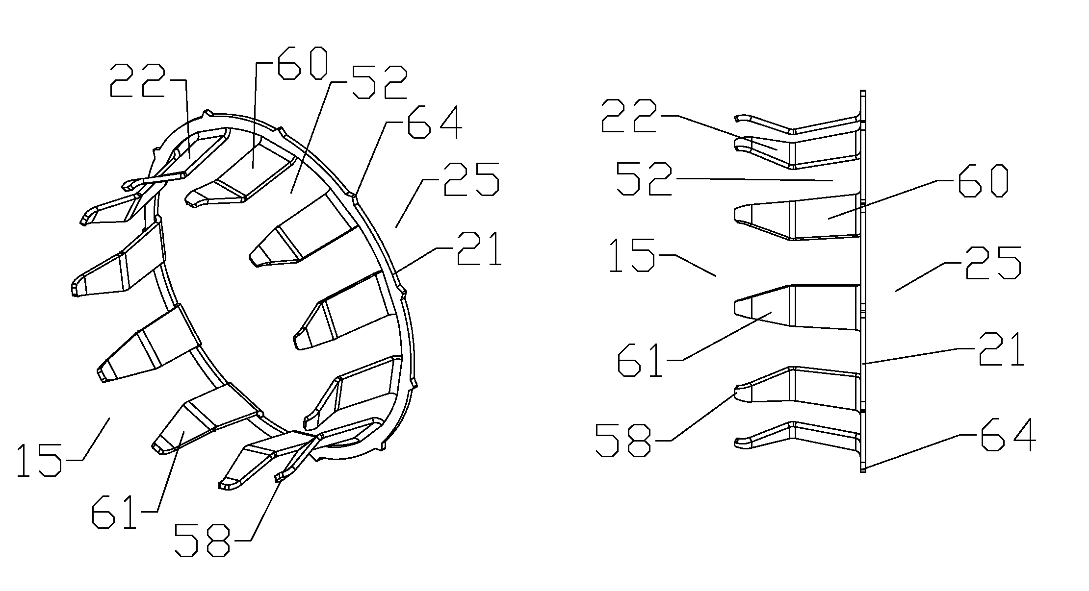
[0050]As best shown in FIG. 20, the spring contact 21 may be cost effectively manufactured with a high level of precision by stamping a pre-form from planar metal sheet material, the spring finger(s) 22 stamped extending radially inward from an inner diameter of a ring. Once stamped, the spring finger(s) 22 of the pre-form are bent into the desired configuration, extending toward the connector end 25 of the resulting spring contact 21. One skilled in the art will appreciate that a diameter of the ring, length of the spring finger(s) 22, and a minimum separation for the stamp tool to define individual spring finger(s) 22 will necessarily limit a spacing of the spring finger(s) 22 circumferentially around the spring contact 21, requiring the presence of significant gap(s) 52 between the spring finger(s) 22, as shown for example in FIGS. 21-23. A length of the spring finger(s) 22 may be extended if a taper is applied proximate a distal end 58 of the spring finger(s) 22.
[0053]The inventors have discovered that, although a ferrous metal may be applied for materials cost purposes, application of a non-ferrous and thus non-magnetic metal, such as phosphor bronze, as the spring contact 21 metal material may significantly improve static passive intermodulation (PIM) characteristics of the resulting coaxial connector 1. The phosphor bronze may be plated, for example with tin, to minimize corrosion.
[0054]To reduce RF leakage through the gap(s) 52, past the spring contact 21 and eventually out the cable end 15 of the coaxial connector 1, the spring contact 21 may be provided as a first ring 54 and a second ring 56 nested together, cable end 15 of the first ring 54 to connector end 25 of the second ring 56, such that the spring finger(s) 22 of each of the first and second rings 54, 56 align contiguously to interleave with one another to form a generally cylindrical surface, as best shown in FIG. 24. To minimize any remaining gap between the interleaved spring finger(s) 22, the gap(s) 52 may be dimensioned to closely mate with the corresponding spring finger(s) 22, for example, provided generally equal to a width of the spring finger(s) 22.
[0056]As best shown in FIGS. 25-27, the nested spring contact 21 provides a significantly reduced RF leakage pathway and an enhanced electrical contact between the outer conductor 11 and the connector body 3 over a range of outer conductor diameters.
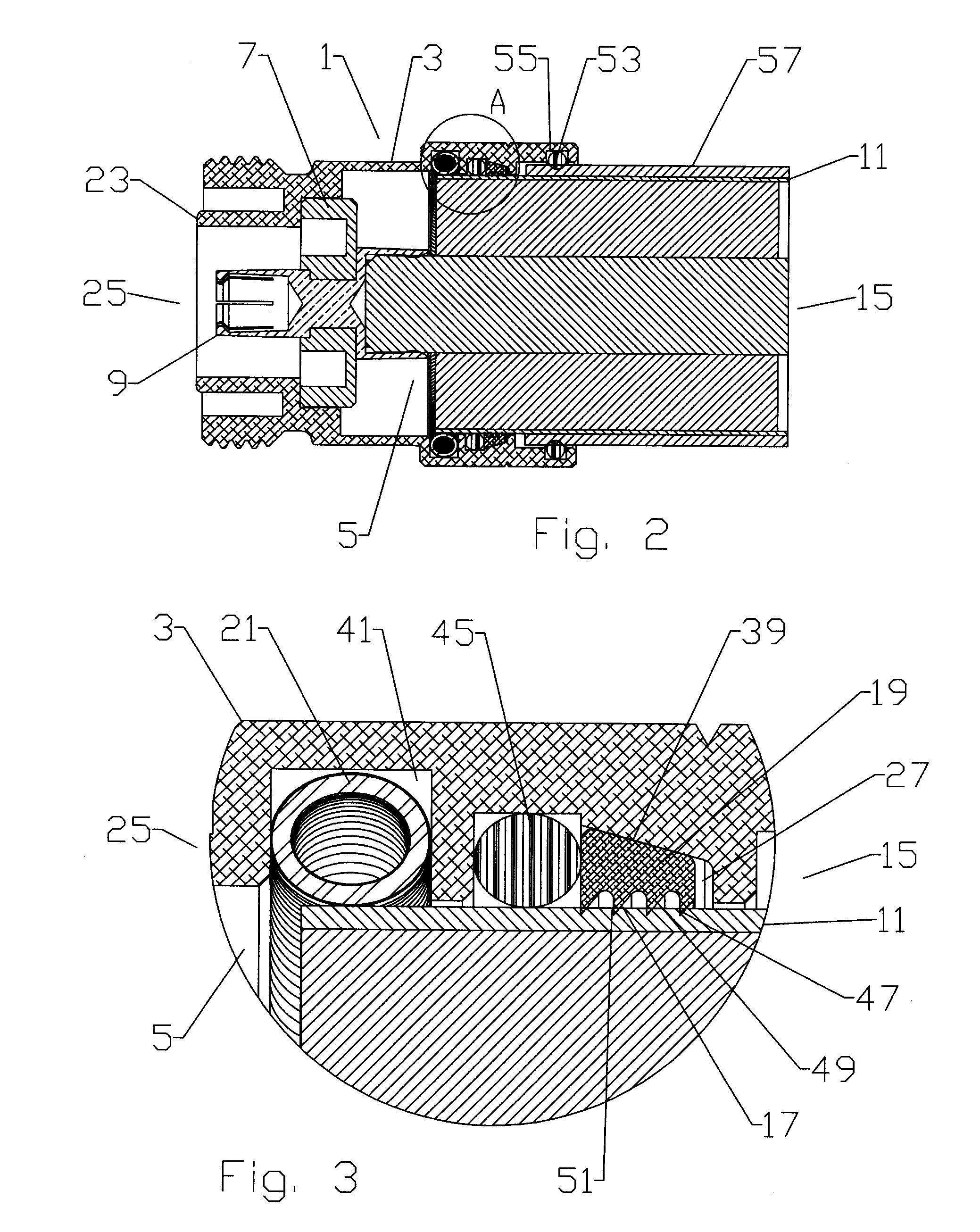
[0062]During cable assembly on embodiments with a clamp ring 31 and a retaining feature 29 including the clamp ring threads 37, the limited longitudinal movement obtained by threading the clamp ring 31 into the connector body 3 is operative to drive the wedge surface 39 against the grip ring 19 to move the grip ring 19 radially inward into secure gripping engagement with the outer conductor 11, without requiring the application of tension between the connector body 3 and the coaxial cable 13. Further, in embodiments where the spring contact 21 is also present in the grip ring groove 27, the threading of the clamp ring 31 into the connector body bore 5 may be configured to apply directly, and / or via a spacer 43, if present, pressure on the spring contact 21 whereby the spring contact 21 deforms radially inward toward the outer conductor 11, increasing the contact pressure between the spring contact 21 and the outer conductor 11, thereby improving the electrical coupling therebetween.

