Coaxial connector for cable with a solid outer conductor

a coaxial cable and outer conductor technology, applied in the direction of connections, basic electric elements, electric devices, etc., can solve the problems of increasing manufacturing costs and installation time requirements, crimping and/or compression becomes impractical with larger diameter coaxial cables

Active Publication Date: 2010-10-05
COMMSCOPE TECH LLC
View PDF21 Cites 24 Cited by
  • Summary
  • Abstract
  • Description
  • Claims
  • Application Information

AI Technical Summary

Benefits of technology

[0037]Clamp ring threads 37 between the connector body bore 5 and an outer diameter of the clamp ring 31 may also be provided as an alternative to the retaining feature 29. To enable the coaxial connector 1 to be supplied as a ready for installation assembly, the clamp ring threads 37 may be combined with the snap groove 33 and snap 35 interconnection to provide an assembly that may be supplied with the clamp ring 31 already attached to the connector body 3, preventing disassembly and / or loss of the internal elements, as shown for example in FIGS. 6-9 and 19-20. Where the retaining feature 29 combines the clamp ring threads 37 with the snap groove 33 and snap barb 35, the longitudinal travel of the clamp ring 31 with respect to the connector body 3 via threading along the clamp ring threads 37 is limited by a width within the snap groove 33 across which the snap barb 35 may move before interfering with the snap groove 33 sidewalls.
[0044]During cable assembly on embodiments with a clamp ring 31 and a retaining feature 29 including the clamp ring threads 37, the limited longitudinal movement obtained by threading the clamp ring 31 into the connector body 3 is operative to drive the wedge surface 39 against the grip ring 19 to move the grip ring 19 radially inward into secure gripping engagement with the outer conductor 11, without requiring the application of tension between the connector body 3 and the coaxial cable 13. Further, in embodiments where the spring contact 21 is also present in the grip ring groove 27, the threading of the clamp ring 31 into the connector body bore 5 may be configured to apply direct and / or via a spacer 43, if present, pressure on the spring contact 21 whereby the spring contact 21 deforms radially inward towards the outer conductor 11, increasing the contact pressure between the spring contact 21 and the outer conductor 11, thereby improving the electrical coupling therebetween.
[0049]One skilled in the art will appreciate the significant manufacturing and installation benefits of the present invention. During manufacturing, a complete coaxial connector 1 assembly ready for installation is prepared with a minimal total number of required elements. If a clamp ring 31 is included in the configuration, the installation of the spring contact 21, spacer 43, grip ring 19 and / or outer conductor seal 45 is simplified by the improved access to the grip ring groove 27, that may then be easily closed by snapping / threading the clamp ring 31 in place after the desired sub elements have been seated in the open end(s) of the connector body bore 5 and / or clamp ring 31. Further, the various environmental seals (outer conductor seal 45, jacket seal 53 and or clamp ring seal 59) may be each overmolded upon the respective groove(s) to provide a single assembly with integral environmental seals. Hole(s) 62 may be formed from the outer diameter to the inner diameter of the clamp ring 31, enabling the outer conductor seal 45 and clamp ring seal 59 to overmolded as a unitary inter-supporting gasket, best shown in FIG. 20. The additional retention of the outer conductor seal 45 provided by overmolding through the hole(s) 62 also enables an outer conductor seal 45 profile with a wiper extension 65. The wiper extension 65 enables the outer conductor seal 45 to more securely seal against both smooth and corrugated outer conductor coaxial cable(s) 13. A further overmolding may be applied in the form of a clamp ring grip 63, for example as shown in FIGS. 18 and 19, on an outer diameter of the clamp ring 31 for improved installer grip during hand threading of the clamp ring 31 into the connector body 3.

Problems solved by technology

Machine threaded coupling surfaces between the metal body and the coupling nut of U.S. Pat. No. 5,795,188 and similarly configured prior coaxial connectors significantly increase manufacturing costs and installation time requirements.
Another drawback is the requirement for connector disassembly, sliding the back body over the cable end and then performing a precision cable end flaring operation, which retains the cable within the connector body during threading.
Further, crimping and / or compression becomes impractical with larger diameter coaxial cables, as the increased diameter, sidewall thickness and / or required travel of the corresponding connector / back body(s) increases the required force(s) beyond the levels deliverable by conventional crimp / compression hand tools.

Method used


Image

  • Coaxial connector for cable with a solid outer conductor
  • Coaxial connector for cable with a solid outer conductor
  • Coaxial connector for cable with a solid outer conductor

Examples


Embodiment Construction

[0031]The inventor has analyzed available solid outer conductor coaxial connectors and recognized the drawbacks of threaded inter-body connection(s), manual flaring installation procedures and crimp / compression coaxial connector designs.

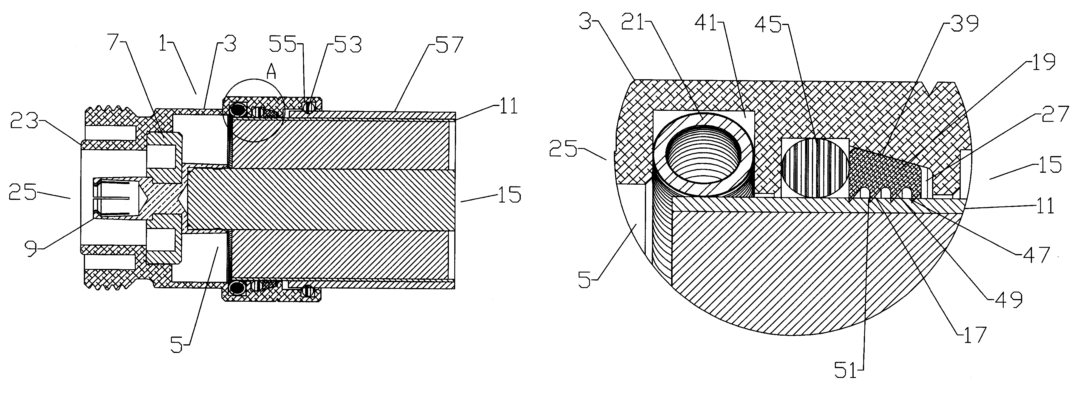
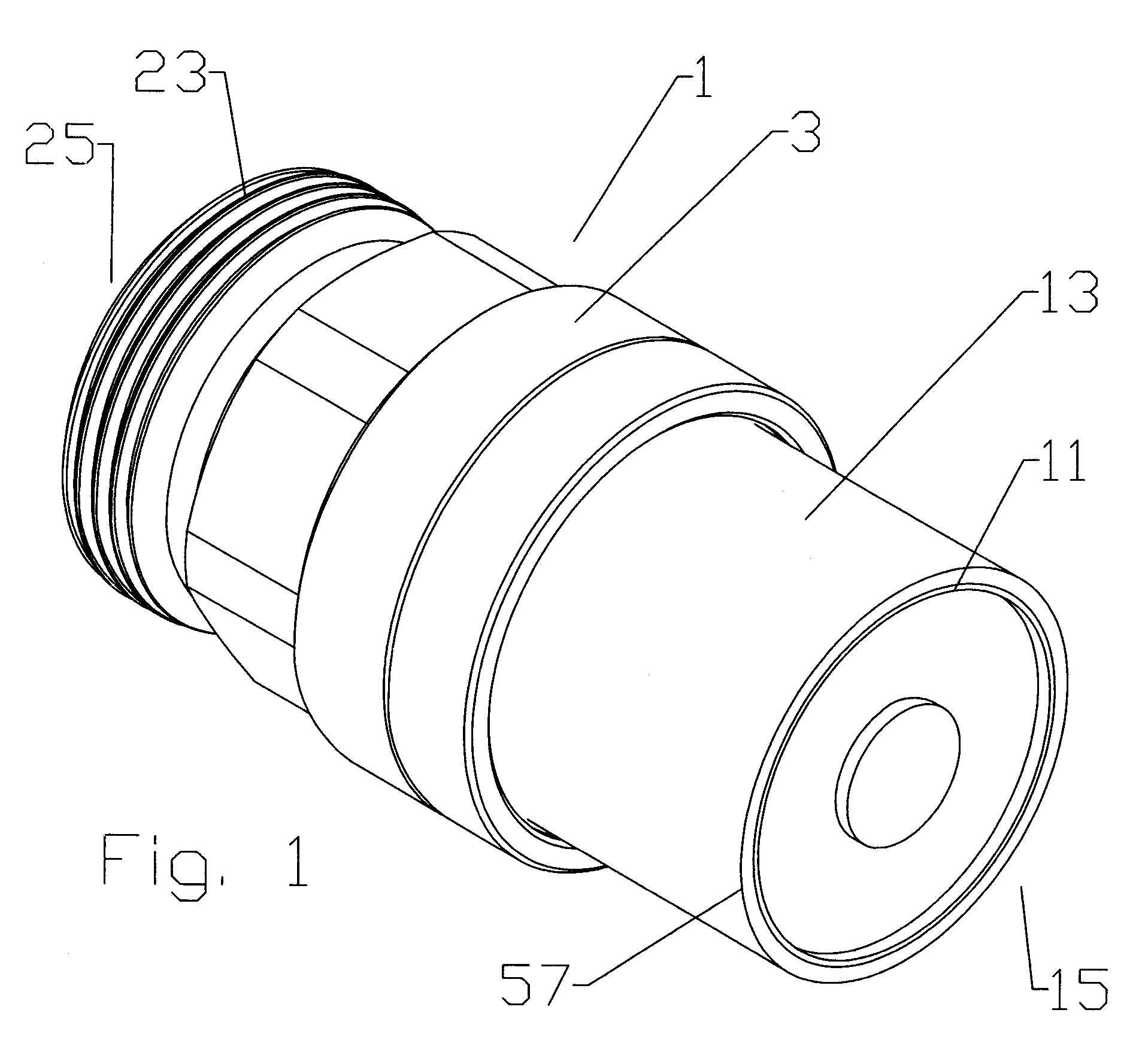
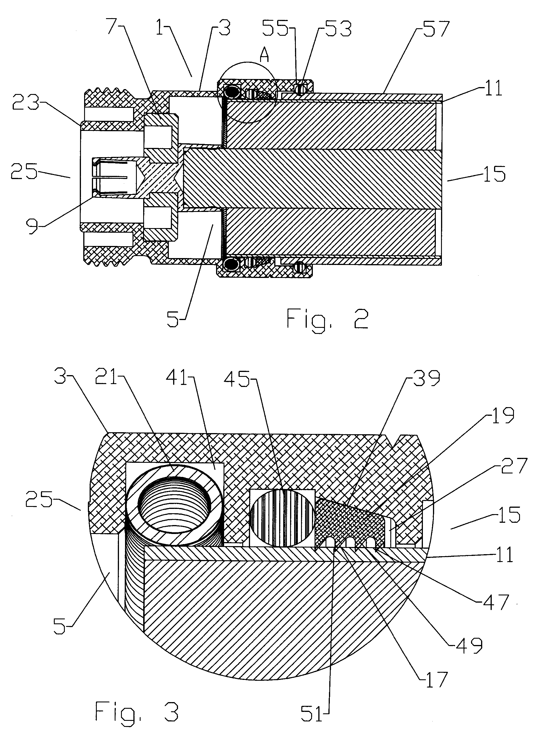
[0032]As shown in a first exemplary embodiment in FIGS. 1-3, a coaxial connector 1 according to the invention has a connector body 3 with a connector body bore 5. An insulator 7 seated within the connector body bore 5 supports an inner contact 9 coaxial with the connector body bore 5. The coaxial connector 1 mechanically retains the outer conductor 11 of a coaxial cable 13 inserted into the cable end 15 of the connector body bore 5 via a grip surface 17 located on the inner diameter of a grip ring 19. A spring contact 21 seated within the connector body bore 5 makes circumferential contact with the outer conductor 11, electrically coupling the outer conductor 11 across the connector body 3 to a connector interface 23 at the connector end 25.

[0033]The...


PUM


Abstract

A coaxial connector with a connector body is provided with a connector body bore. A grip ring is retained within the connector body bore, and an outer diameter of the grip ring abuts an annular wedge surface provided with a taper between a maximum diameter proximate the connector end and a minimum diameter proximate the cable end. The wedge surface may be provided directly on the connector body bore sidewall or alternatively on an inner diameter of a clamp ring coupled to the cable end of the connector body. An inner diameter of the grip ring is provided with a grip surface. A spring contact is retained within the connector body bore. The grip surface and an inner diameter of the spring contact are dimensioned to receive the outer conductor from the cable end there through and to then couple with an outer diameter of the outer conductor.

Description

BACKGROUND[0001]1. Field of the Invention[0002]This invention relates to electrical cable connectors. More particularly, the invention relates to a solid outer conductor coaxial cable connector coupled to a coaxial cable by insertion of the cable end into a connector body bore.[0003]2. Description of Related Art[0004]Coaxial cable connectors are used, for example, in communication systems requiring a high level of precision and reliability.[0005]To create a secure mechanical and optimized electrical interconnection between the cable and the connector, it is desirable to have generally uniform, circumferential contact between a leading edge of the coaxial cable outer conductor and the connector body. A flared end of the outer conductor may be clamped against an annular wedge surface of the connector body, via a coupling nut. Representative of this technology is commonly owned U.S. Pat. No. 5,795,188 issued Aug. 18, 1998 to Harwath.[0006]Machine threaded coupling surfaces between the ...

Claims


Application Information

Patent Timeline
Patent Type & Authority Patents(United States)
IPC IPC(8): H01R9/05
CPCH01R9/0521H01R4/5025
Inventor PAYNTER, JEFFREYCOX, AL
Owner COMMSCOPE TECH LLC
Why Eureka
Try Eureka