Torque testing device

a torque wrench and torque technology, applied in the field of torque testing devices, can solve the problem of inaccurate torque testing with the torque wrench

Inactive Publication Date: 2013-06-04
HONG FU JIN PRECISION IND (SHENZHEN) CO LTD +1
View PDF12 Cites 14 Cited by
  • Summary
  • Abstract
  • Description
  • Claims
  • Application Information

AI Technical Summary

Benefits of technology

[0004]Usually, the proof or yield strength (anti-torque strength) of a screw or a bolt is tested by a torque wrench. During testing, the screw or the bolt is twisted into a threaded hole by the torque wrench. The torque wrench simultaneously provides a lateral force and a torque to the screw or the bolt. However, the screw or the bolt is likely to be tilted by the torque wrench, and torque testing by the torque wrench is not accurate when the screw or the bolt is tilted.

Problems solved by technology

However, the screw or the bolt is likely to be tilted by the torque wrench, and torque testing by the torque wrench is not accurate when the screw or the bolt is tilted.

Method used


Image

  • Torque testing device
  • Torque testing device
  • Torque testing device

Examples


Embodiment Construction

[0013]Embodiments of the present disclosure will now be described in detail with reference to the drawings.

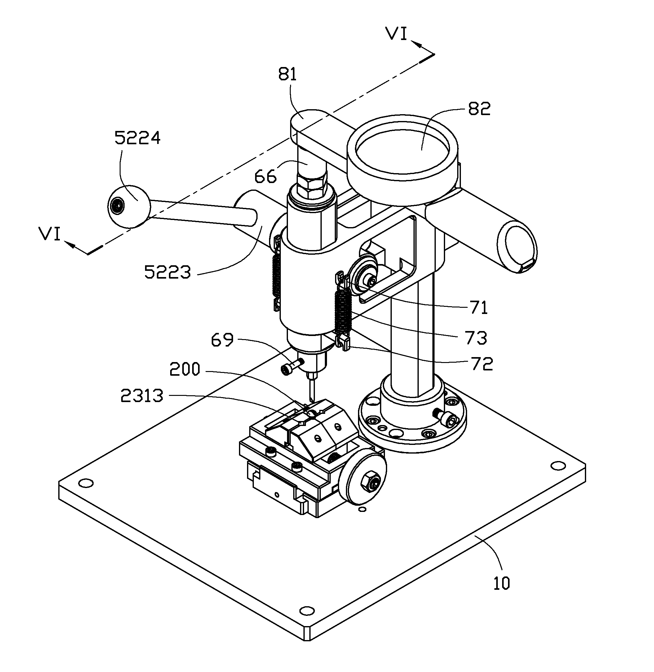
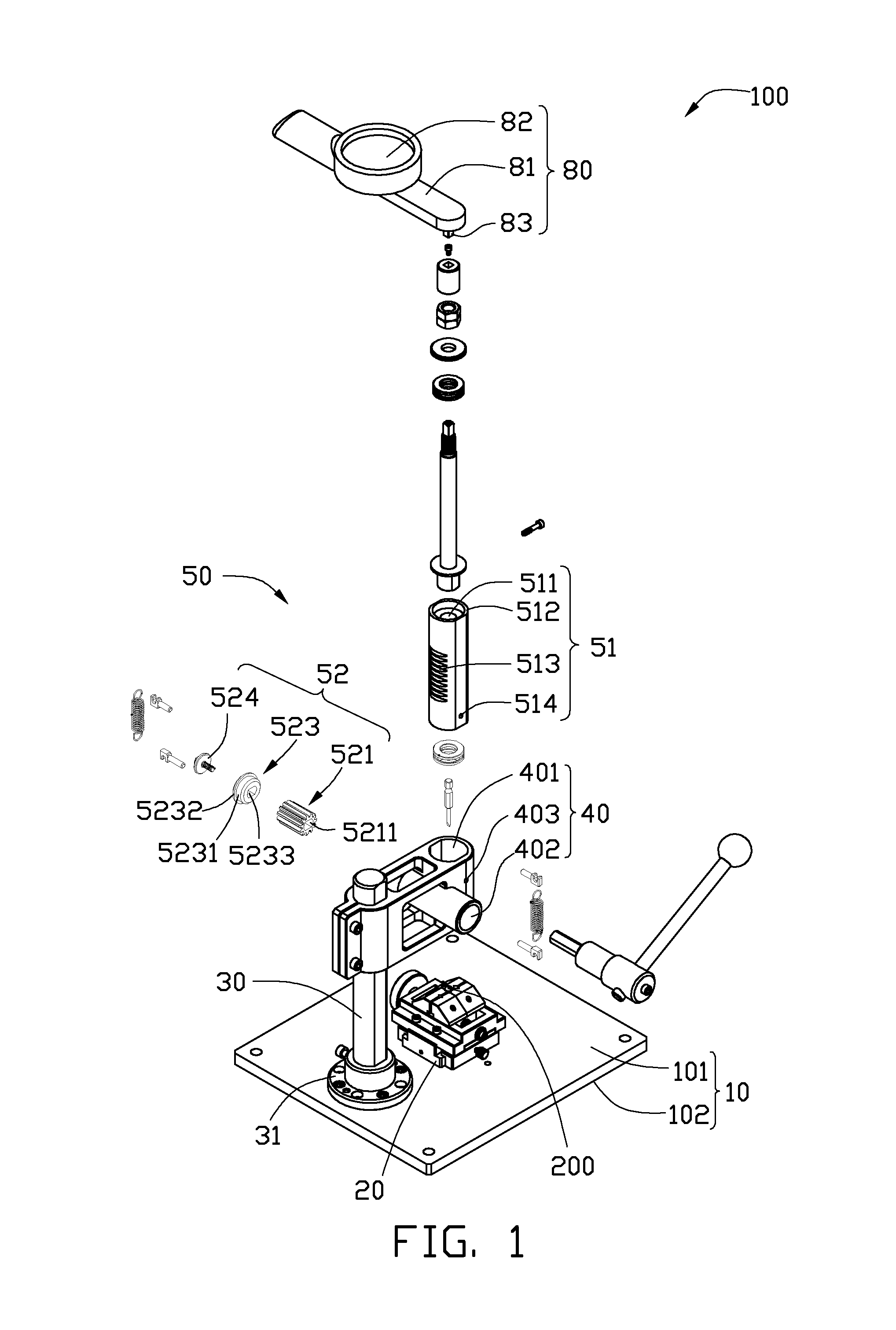
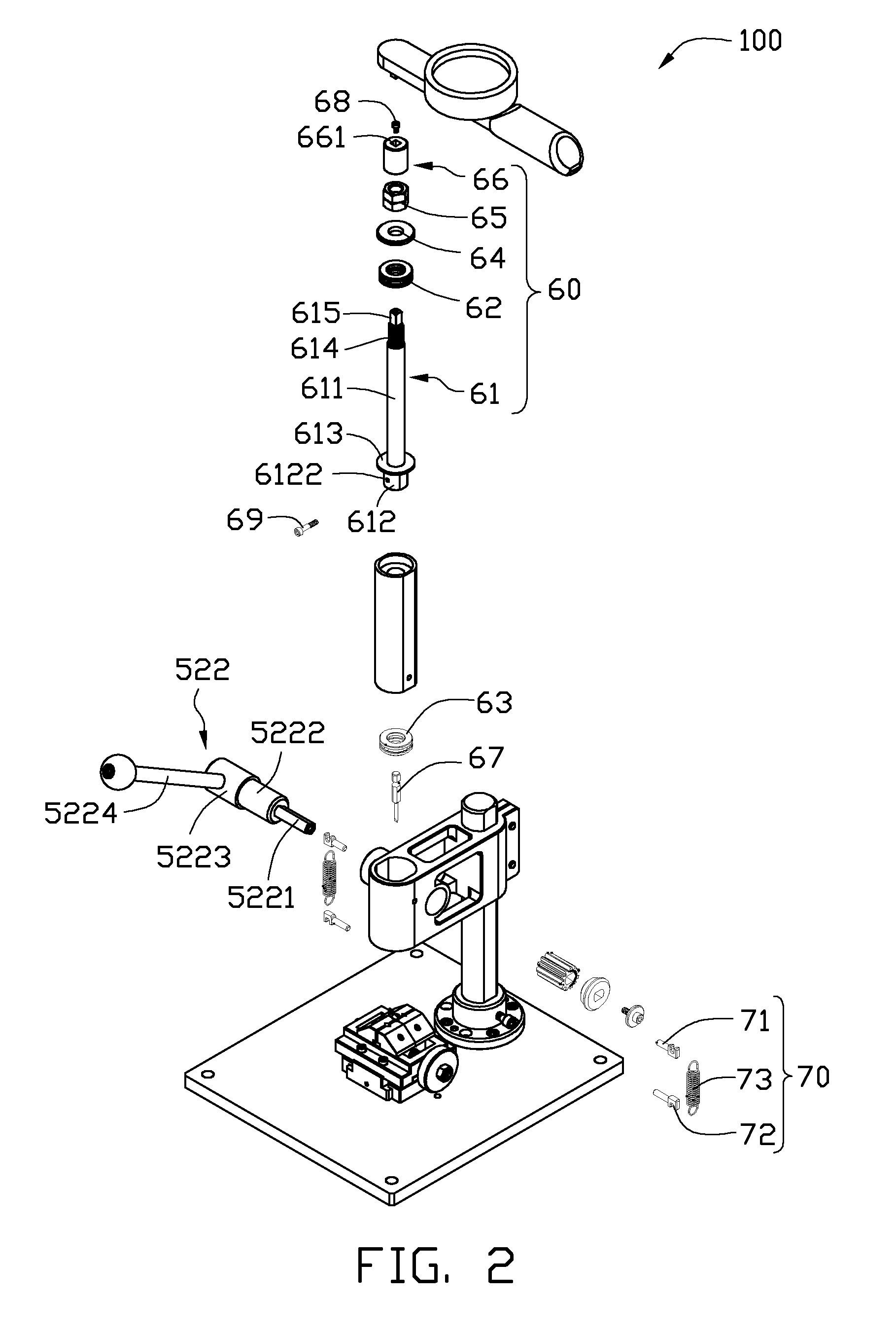
[0014]Referring to FIGS. 1 and 2, a torque testing device 100 for testing or proving the yield strength (anti-torque strength) of a fastener 200, according to an exemplary embodiment, includes a base 10, a clamping device 20, a holding cylinder 30, a mounting beam 40, a moving component 50, a rotation component 60, two reposition components 70, and a torque wrench 80. In this embodiment, the fastener 200 is a screw.

[0015]The base 10 is generally a rectangular plate and includes a flat top surface 101 and a bottom surface 102 opposite to the top surface 101.

[0016]Referring to FIGS. 3 and 4, the clamping device 20 includes a supporting base 21, a frame member 22, two slidable members 23 and a bolt 24. The supporting base 21 is positioned on the top surface 101. The frame member 22 is mounted on the supporting base 21 and includes a pair of first sidewalls 221, a pair of second si...


PUM

PropertyMeasurementUnit
torque testingaaaaaaaaaa
torqueaaaaaaaaaa
diameteraaaaaaaaaa

Abstract

A torque testing device includes a base, a clamping device for clamping a fastener, a holing cylinder mounted on the base, a mounting beam mounted on the holding cylinder, a moving component, a rotation component, and a torque wrench. The mounting beam defines a nesting hole. The moving component includes a tubular member received in the nesting hole and a driving component mounted on the mounting beam for driving the tubular member towards the fastener. The rotation component includes a rotation shaft and at least one rotation element positioned between the rotation shaft and the tubular member. The rotation shaft is moved with the tubular member towards the fastener. The rotation shaft is capable of being rotated about the tubular member through the rotation element. The torque wrench is connected to the rotation shaft for applying torque to the rotation shaft and revealing the value of the torque.

Description

BACKGROUND[0001]1. Technical Field[0002]The present disclosure relates to testing devices and, particularly, to a torque testing device.[0003]2. Description of Related Art[0004]Usually, the proof or yield strength (anti-torque strength) of a screw or a bolt is tested by a torque wrench. During testing, the screw or the bolt is twisted into a threaded hole by the torque wrench. The torque wrench simultaneously provides a lateral force and a torque to the screw or the bolt. However, the screw or the bolt is likely to be tilted by the torque wrench, and torque testing by the torque wrench is not accurate when the screw or the bolt is tilted.[0005]Therefore, it is desirable to provide a torque testing device, which can overcome the limitations described.BRIEF DESCRIPTION OF THE DRAWINGS[0006]Many aspects of the present disclosure can be better understood with reference to the following drawings. The components in the drawings are not necessarily drawn to scale, the emphasis instead bein...

Claims


Application Information

Patent Timeline
Patent Type & Authority Patents(United States)
IPC IPC(8): G01L3/02G01L3/00
CPCG01L5/0042
Inventor ZHANG, BING-JUN
Owner HONG FU JIN PRECISION IND (SHENZHEN) CO LTD
Why Eureka
Try Eureka