Hair clipper

a clipper and hair technology, applied in the field of hair clippers, can solve the problems of difficult to get an effective acute angle for cutting hair, no disclosure about the blade edges or the rake angle of the blade pieces, and hair b>40/b> cannot be cut efficiently, so as to prevent hair pulling, prevent hair pulling, and cut hair efficiently

Active Publication Date: 2013-07-09
PANASONIC CORP
View PDF15 Cites 21 Cited by
  • Summary
  • Abstract
  • Description
  • Claims
  • Application Information

AI Technical Summary

Benefits of technology

[0006]The present invention provides a hair clipper capable of cutting hair efficiently along the entire projecting direction of the blade piece of the movable blade by guiding the hair introduced into the blade groove to the center portion of the blade groove and preventing the hair from escaping from the blade groove, and preventing hair pulling.
[0008]Since the blade edges of the blade piece are formed in a “<” or “>” shape so that the hair introduced into each blade groove formed between the adjacent blade pieces, when cutting the hair, can be guided to the center portion of the blade groove having a larger groove width. Further, the blade edges of the movable blade, i.e., both the leading rectilinear part and basal rectilinear part of the blade pieces are inclined to the blade edges of the fixed blade through out the entire length thereof by the acute included angle α so that the hair can be cut effectively along the entire projecting direction Y of the blade pieces of the movable blade. Furthermore, the blade edges of the movable blade have the rake surface by an acute angle β throughout the entire length of the leading rectilinear part and the basal rectilinear part. Therefore, it is possible to prevent the hair from being pulled by the blade edges of the movable blade throughout the entire projecting direction Y of the blade pieces of the movable blade.
[0010]In accordance with the present invention, the hair clipper can prevent the hair from coming out of the blade groove by guiding the hair introduced into the blade groove to the center portion of the blade groove, cut the hair efficiently in an entire projecting direction of the blade pieces of the movable blade, and prevent the hair pulling.

Problems solved by technology

As a result, the hair 40 cannot be cut efficiently.
As a result, it is difficult to get an effective acute angle for cutting the hair.
However, there is no disclosure about the blade edges or a rake angle of the blade pieces.

Method used


Image

  • Hair clipper
  • Hair clipper
  • Hair clipper

Examples


Embodiment Construction

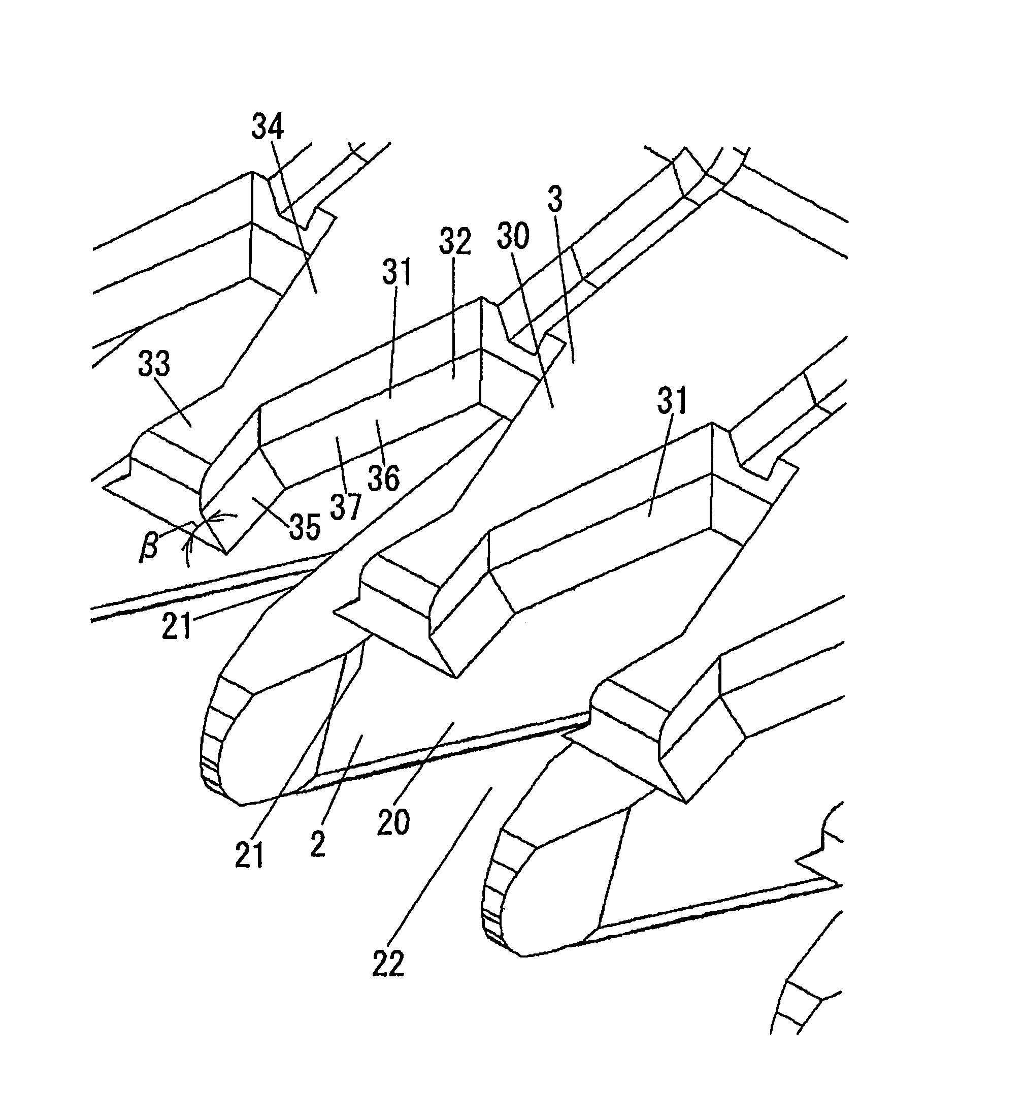
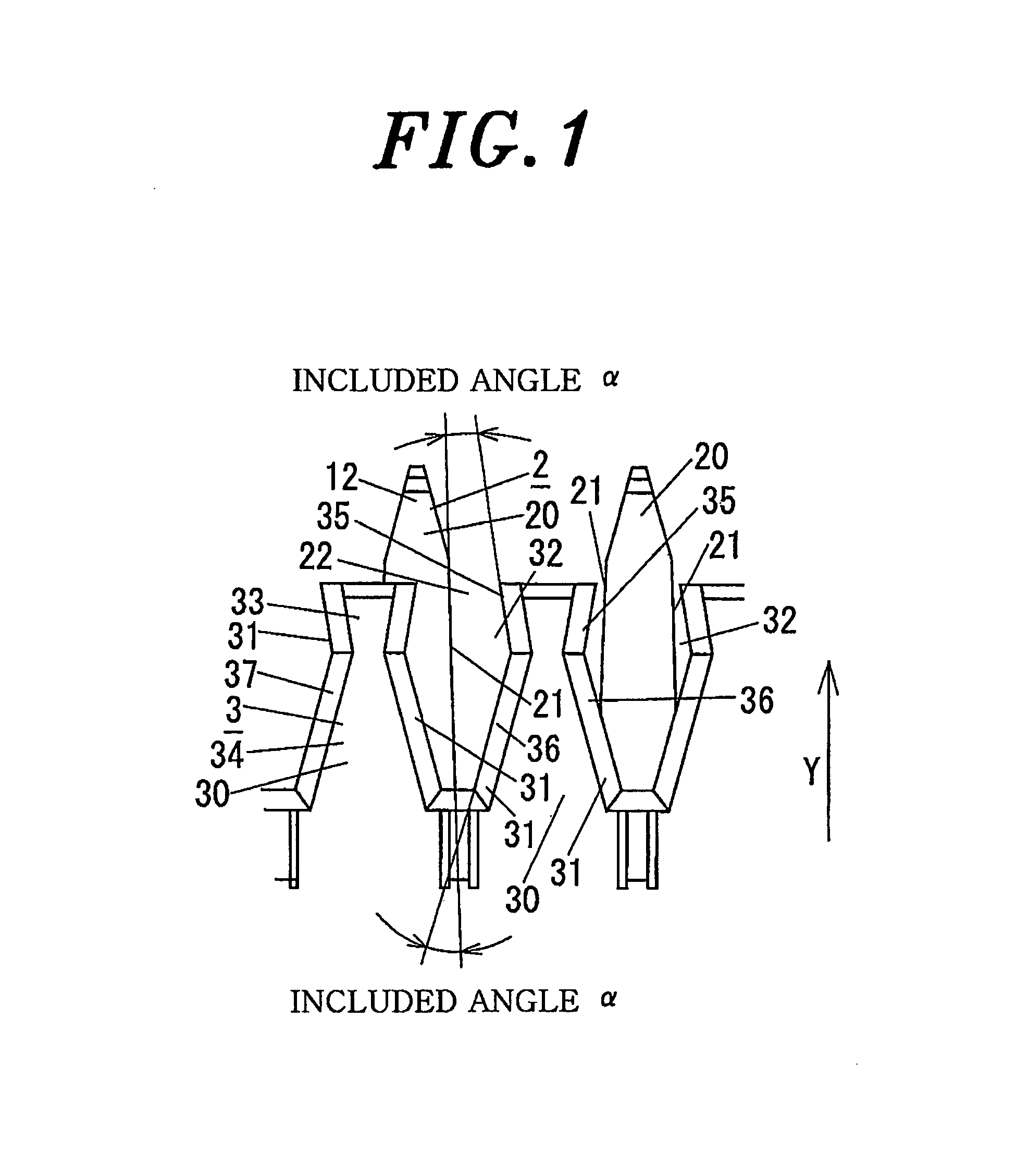
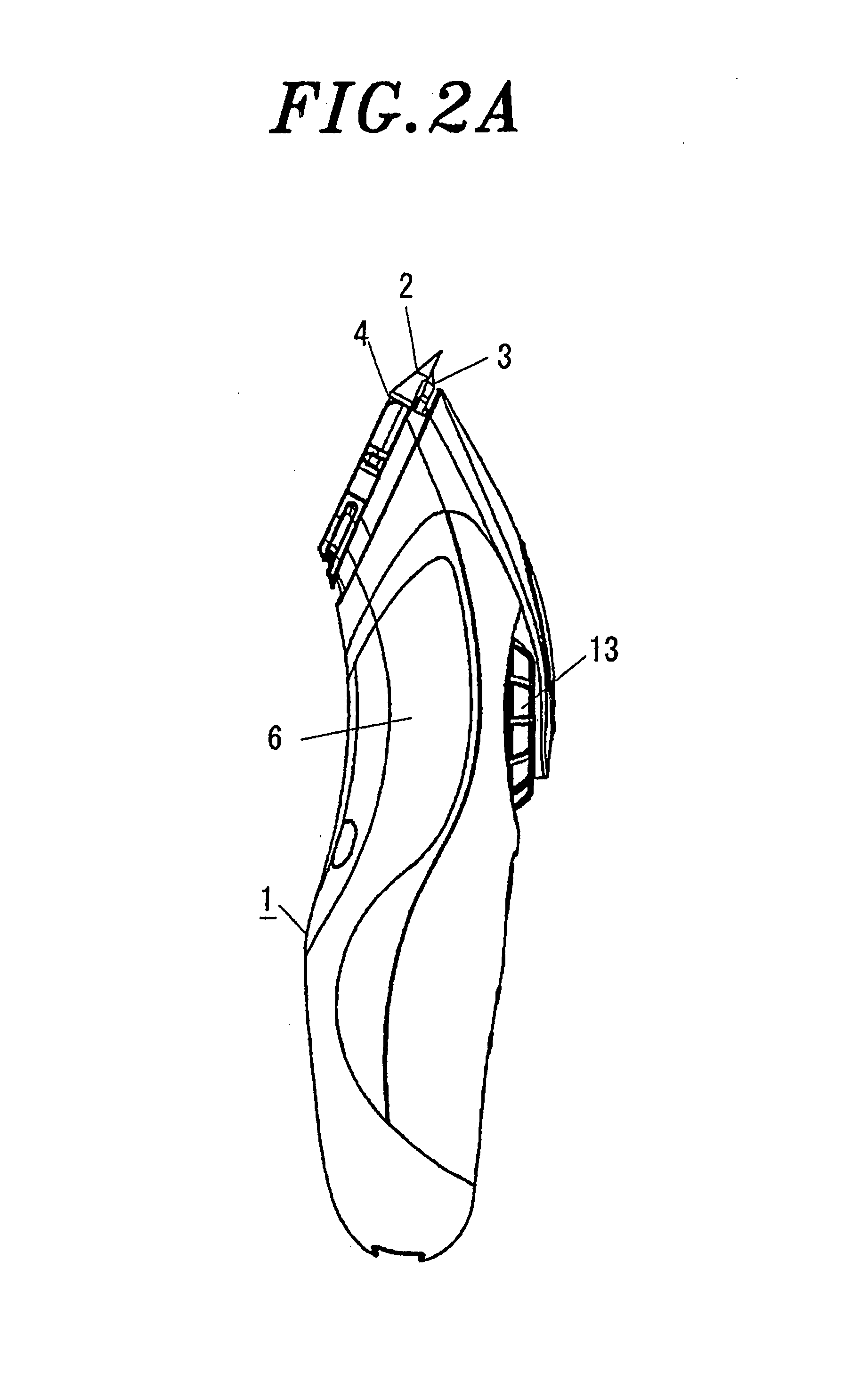
[0022]Hereinafter, embodiments of the present invention will be disclosed with reference to the accompanying drawings. A hair clipper in accordance with an embodiment of the present invention has an elongated main body 1, which also functions as a grip, as shown in FIGS. 2A and 2B. A blade block 4 having a fixed blade 2 and a movable blade 3 is mounted on a leading end of the main body 1 in its longitudinal direction (top end in FIGS. 2A and 2B). The movable blade 3 of the blade block 4 is slidingly reciprocated in the lateral direction (left-right direction in FIG. 2B) with respect to the fixed blade 2 by a motor disposed in the main body 1 as a driving source, so that hair 40 introduced into blade grooves 22 on the tip of the fixed blade 2 is sandwiched between the fixed blade 2 and the movable blade 3 and cut thereby.

[0023]Referring to FIG. 3, the main body 1 has a housing 6 having a substantially S-shaped appearance as viewed from side. A user can grasp the housing 6 with his or...


PUM


Abstract

A hair clipper includes a comb-like fixed blade and movable blade having a plurality of blade pieces arranged in parallel. The fixed blade and the movable blade is overlapped with each other and the movable blade is reciprocatively slid with respect to the fixed blade in an arrangement direction of the blade pieces. Each blade piece of the movable blade has blade edges formed at both sides thereof, each blade edge being formed with a leading rectilinear part and a basal rectilinear part; the leading rectilinear part and the basal rectilinear part are inclined with respect to the blade edges formed at both sides of each blade piece of the fixed blade by an acute included angle α; and each blade edge of the movable blade has a rake surface facing an opposite side to the fixed blade.

Description

FIELD OF THE INVENTION[0001]The present invention relates to a hair clipper for cutting hair by reciprocating a movable blade with respect to a fixed blade.BACKGROUND OF THE INVENTION[0002]Conventionally, there is a known hair clipper including comb-like fixed blade and movable blade having a plurality of blade pieces arranged in parallel. This hair clipper is used for cutting hair by reciprocating the movable blade with respect to the fixed blade in the arrangement direction of the blade pieces.[0003]Conventionally, the blade pieces 30 of the movable blade 3 each have a tapered end portion as shown FIG. 9. However, while sliding the movable blade 3 with respect to the fixed blade, hair 40 introduced into a blade groove 32 between the adjacent blade pieces 30 comes out of the blade groove 32 as indicated by an arrow in the FIG. 9. As a result, the hair 40 cannot be cut efficiently.[0004]Further, for example, Japanese Patent Laid-open Application No. 2000-308768 discloses a circular-...

Claims


Application Information

Patent Timeline
Patent Type & Authority Patents(United States)
IPC IPC(8): B26B19/06B26B19/20
CPCB26B19/06B26B19/3846B26B19/04B26B19/02
Inventor FUKUTANI, MAKOTOIKUTA, TOSHIO
Owner PANASONIC CORP
Why Eureka
Try Eureka