Caster

a caster and caster body technology, applied in the field of casters, can solve the problems of large devices such as cabinets, inconvenient for users, unstable devices and too easily moved devices,

Inactive Publication Date: 2013-07-16
HONG FU JIN PRECISION IND (SHENZHEN) CO LTD +1
View PDF15 Cites 43 Cited by
  • Summary
  • Abstract
  • Description
  • Claims
  • Application Information

AI Technical Summary

Problems solved by technology

A large device, such as a cabinet, is too heavy to move easily from one place to another place.
Typically, wheels are attached to the bottom of the device to more easily move the device, but the wheels may cause the device to be unstable and too easily moved as well.
Therefore, it is inconvenient for users, when the device does not need to be moved.

Method used


Image

  • Caster
  • Caster
  • Caster

Examples


Embodiment Construction

[0010]The disclosure, including the accompanying drawings in which like references indicate similar elements, is illustrated by way of examples and not by way of limitation. It should be noted that references to “an” or “one” embodiment in this disclosure are not necessarily to the same embodiment, and such references mean at least one.

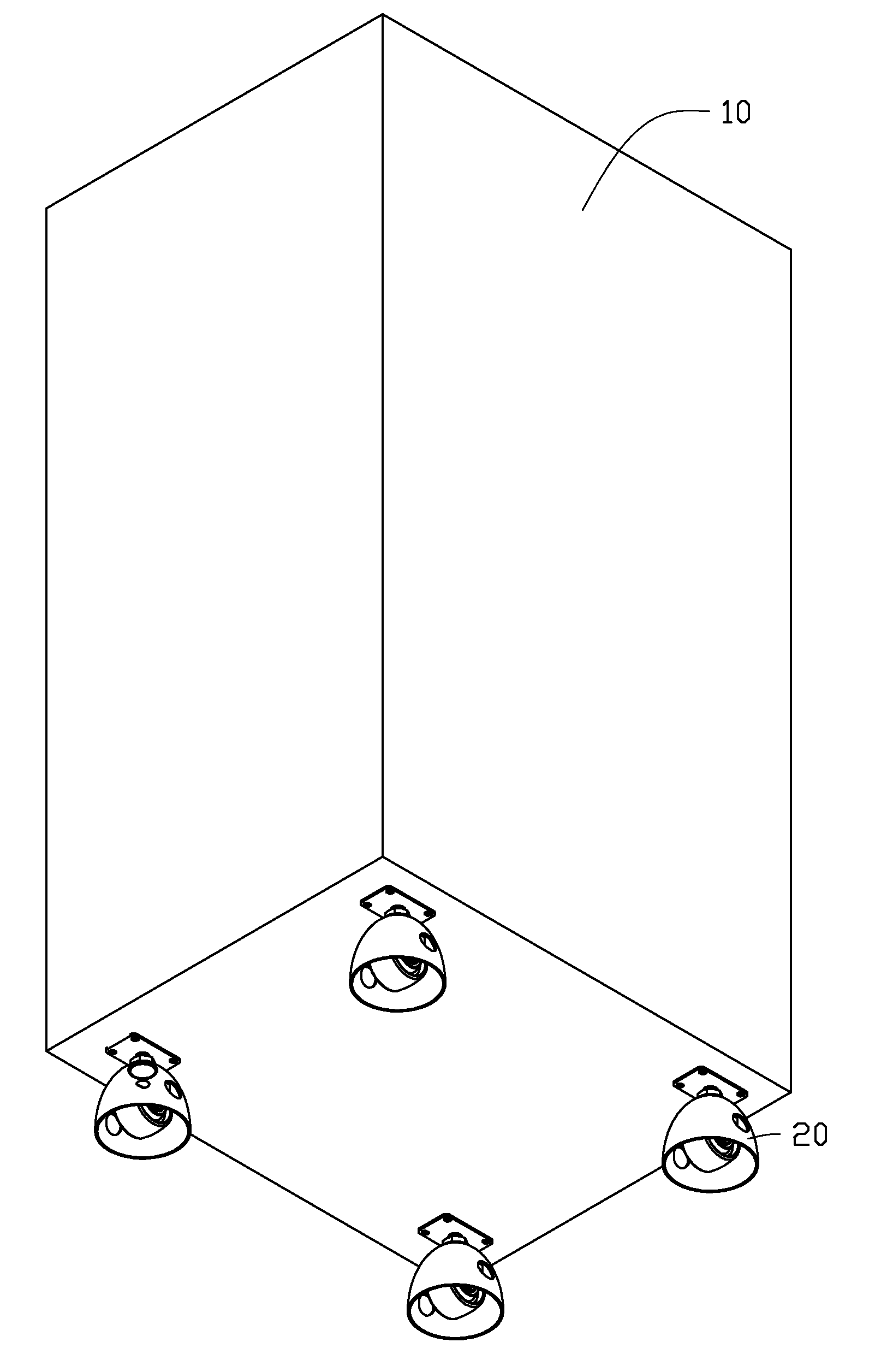
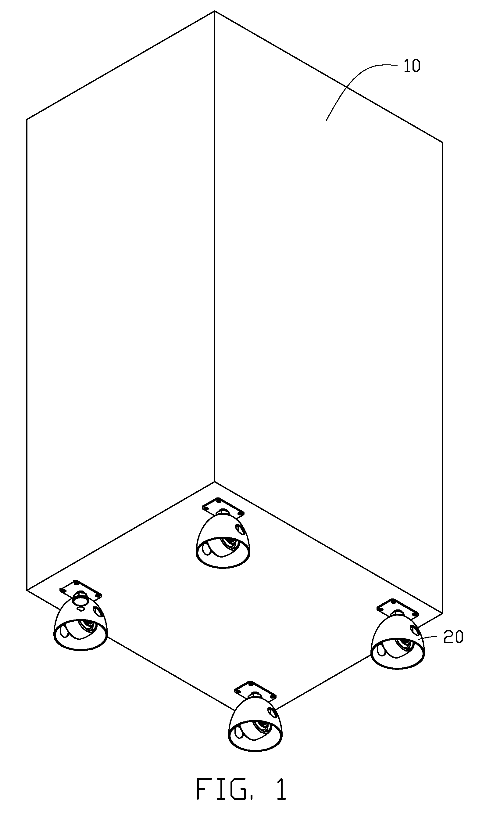
[0011]Referring to FIGS. 1 and 2, in an exemplary embodiment, a caster 20 is provided to be mounted to a bottom of a device 10. In this embodiment, the device 10 is a serving cabinet.

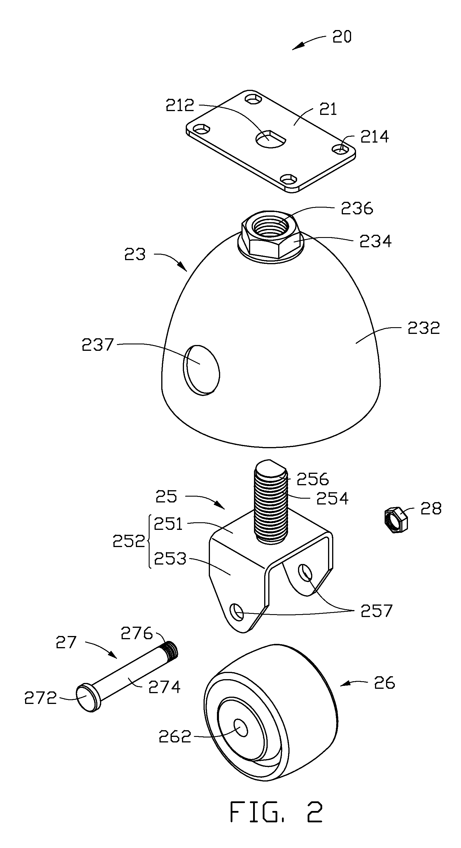
[0012]The caster 20 includes a fixing board 21, a support 23, a connecting member 25 which is threadedly connected to the support 23, a wheel 26, a fast pin 27, and a nut 28.

[0013]The fixing board 21 defines a D-shaped fastening hole 212 in a center of the fixing board 21, and a plurality of fixing holes 214 in corners of the fixing board 21.

[0014]The support 23 includes a lampshade shaped main body 232, with a circular opening (not labeled) defined in a bottom of the mai...


PUM


Abstract

A caster for being mounted to a bottom of a device includes a support, a connecting member, and a wheel mounted to the connecting member. The support defines a receiving space. The connecting member is threadedly connected to the support, and comprises a bracket accommodated in the receiving space. The wheel is rotatably mounted to the bracket. The support and the connecting member are operable to rotate relative to each other, with the wheel moving to expose out of or retract inside the receiving space.

Description

BACKGROUND[0001]1. Technical Field[0002]The disclosure relates to casters, and more particularly to a caster attached to a cabinet for convenient moving and stabilizing of the cabinet.[0003]2. Description of Related Art[0004]A large device, such as a cabinet, is too heavy to move easily from one place to another place. Typically, wheels are attached to the bottom of the device to more easily move the device, but the wheels may cause the device to be unstable and too easily moved as well. Therefore, it is inconvenient for users, when the device does not need to be moved.BRIEF DESCRIPTION OF THE DRAWINGS[0005]Many aspects of the present embodiments can be better understood with reference to the following drawings. The components in the drawings are not necessarily drawn to scale, the emphasis instead being placed upon clearly illustrating the principles of the present embodiments. Moreover, in the drawings, all the views are schematic, and like reference numerals designate correspondi...

Claims


Application Information

Patent Timeline
Patent Type & Authority Patents(United States)
IPC IPC(8): B60B33/06
CPCB60B7/02B60B7/061B60B7/14B60B33/0007B60B33/0018B60B33/0039B60B33/0063B60B33/0089B60B33/063B60B33/0049Y10T16/184Y10T16/182Y10T16/193Y10T16/216
Inventor LI, XIAO-ZHENGPENG, WEN-TANG
Owner HONG FU JIN PRECISION IND (SHENZHEN) CO LTD
Why Eureka
Try Eureka