Compressible device

a compression device and electrode technology, applied in the direction of internal electrodes, digestive electrodes, therapy, etc., can solve the problems of inability to easily insert the electro-stimulation device of these dimensions into the vagina or anus for use, no means provided for the re-programming of the internal microprocessor controlled circuitry, etc., to achieve the effect of convenient inserting into the vagina or anus

Inactive Publication Date: 2013-08-13
FEMEDA LTD
View PDF114 Cites 20 Cited by
  • Summary
  • Abstract
  • Description
  • Claims
  • Application Information

AI Technical Summary

Benefits of technology

[0019]In a further embodiment the electro-stimulation device body may be compressible due to a combination of the choice of materials used for its manufacture and due to its structure. For example the electro-stimulation device body may be manufactured from resiliently deformable material and the interior of the electro-stimulation device body may be hollow. In this embodiment when the electro-stimulation device is compressed the body material is deformed and the hollow interior may be constricted or collapsed to a smaller volume. This combination may provide for an electro-stimulation device with a high magnitude of reversible compressibility so that the electro-stimulation device may be compressed to a significantly smaller volume compared to the non-compressed state.
[0028]Thus the electro-stimulation device of the present invention may be adapted for deployment into an anal or vaginal endocavity via the use of an applicator. The applicator may for example be a hollow tubular applicator containing the electro-stimulation device in its bore in the compressed state. The device is deployed from the applicator into the vagina or anus. Typically the applicator including compressed device is positioned at the vaginal introitus (opening) or anal sphincter and the device is then discharged from the applicator into the anus or vagina by operation of the plunger. Once inside the vagina or anus the compressed electro-stimulation device may expand.
[0031]In a preferred embodiment the inner member is adapted to assist with activation of the electro-stimulation device as it is deployed from the applicator. In this embodiment adaptation may take the form of a specific shape or arrangement of the proximate end of the inner member so that it comes into contact with part of the activation mechanism for the electro-stimulation device. During deployment of the electro-stimulation device from the applicator the inner member makes contact with and remains in contact with this activation mechanism until the device is deployed. It is the contact between the proximate end of the inner member and the activation mechanism coupled with a requisite amount of stiction between the electro-stimulation device and the outer member of the applicator that ensures that enough force is applied to the activation mechanism during deployment to activate the device. The force required to activate the activation mechanism through this contact is less than the force required to overcome the stiction between the outer member and enclosed electro-stimulation device. This means that the force applied to the inner member during deployment will activate the activation mechanism before the inner member through applied pressure forces the electro-stimulation device out of the outer member and into the endocavity. The preferred activation mechanism associated with use of the applicator will be described in more detail below. In a preferred embodiment the applicator comprises a detent position, which assists in preventing inadvertent activation of the electro-stimulation device during manufacture, storage or unpacking by the end user. A reasonable force must be applied to the inner member to disengage this detent and allow the inner member to move relevant to the outer member. In a further preferred embodiment the inner member is in the form of a hollow tube. This arrangement has the advantage that a withdrawal cord when used is able to pass down the bore of the tube and is thus protected from being trapped between the inner and outer members during deployment of the device. This arrangement also assists with alignment during assembly of the applicator incorporating the electro-stimulation device.
[0036]In a preferred embodiment all of the electrical components of the electronic sub-assembly apart from the electro-conductive elements and associated wiring but including the activation mechanism are enclosed in whole or in part within a chassis. The interior of the chassis is able to accommodate the PCB and through appropriately located orifices is able to allow the conductive paths to pass from the device body into the chassis to make electrical contact with the PCB. Preferably at one end of the chassis there is an opening which may accommodate the activation means for the device. The activation mechanism may be partly enclosed within the chassis. In a preferred embodiment the chassis comprises two components that reversibly engage with each other to provide an enclosed section of the chassis and providing an open section of the chassis. The PCB is preferably located within the enclosed section and the activation means is associated with both the closed and open sections. The activation means will be described more fully below. The benefit of the enclosed section of the chassis is that it is able to protect the sensitive components of the PCB during manufacture of the device or its use and from ingress of liquid. It has the further advantage of preventing or limiting egress of material from the components within the chassis. Preferably the chassis is manufactured from polypropylene or ABS (acrylonitrile butadiene styrene) polymers. During manufacture of the device the chassis comprising the PCB and activation mechanism may easily be inserted and bonded into a pre-moulded cavity within the moulded device body. This cavity being in communication with other smaller cavities that accommodate the surface exposed electro-conductive elements and their conductive paths such as wiring. This arrangement provides an easy means for assembly of the device from the individual components to provide a robust device.

Problems solved by technology

Preferably the electro-stimulation device does not have any means for enabling the enclosed battery or batteries to be replaced or re-charged.
There is no means provided for the re-programming of the internal microprocessor controlled circuitry e.g. control unit and / or signal generator to provide a different electro-stimulation regime as this is pre-programmed into the device.
Normally, an electro-stimulation device of these dimensions could not easily be inserted into the vagina or anus for use.

Method used


Image

  • Compressible device
  • Compressible device
  • Compressible device

Examples


Embodiment Construction

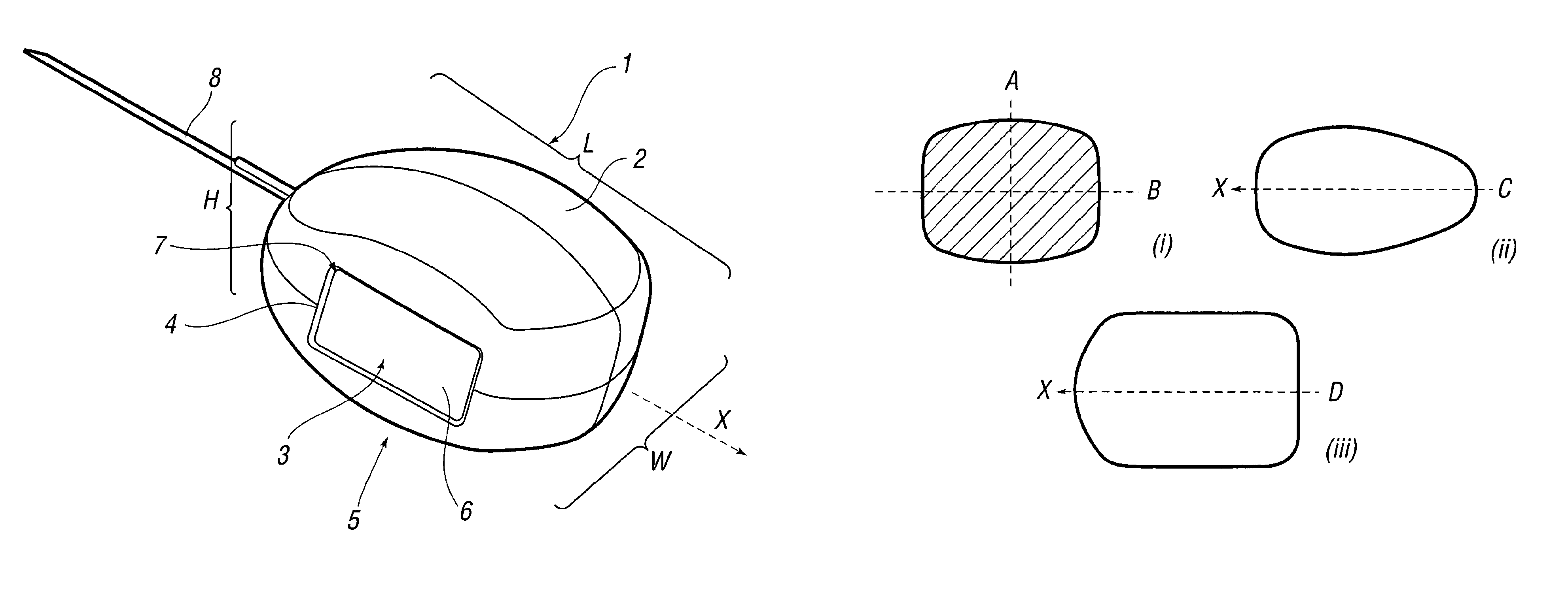
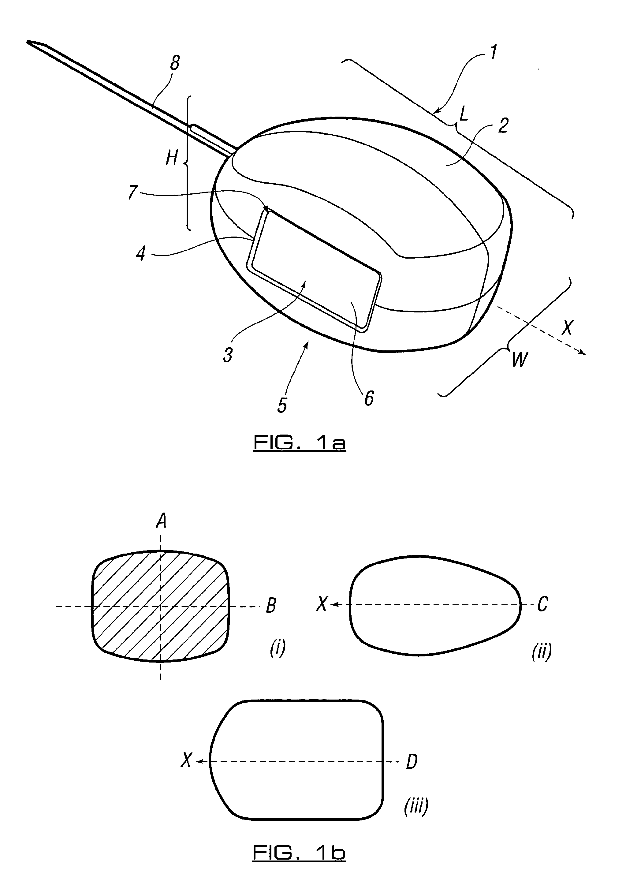
[0062]Referring to FIG. 1 (a) an electro-stimulation device (1) is shown in the non-compressed, fully expanded state. The device (1) has a body (2) which has been constructed from bio-compatible resiliently compressible foam. Electrode components hereinbefore and after also referred to as electro-conductive elements (3 and 3′ not shown) emerge from within the body (2) of the device and are located at the surfaces (4 and 4′ not shown) on sides (5 and 5′ not shown) of the device (1). The electro-conductive elements (3 and 3′ not shown) are relatively flat. In this particular embodiment the electrode components (3, 3′) are in communication with the internal components (not shown) of the device (1) through internal conductive paths. They pass from within the device (1) to provide electrode surfaces (6 and 6′ not shown) that are located in approximately the same plane as the surfaces (4, 4′) of the sides (5, 5′) of the device. The main body of the flat electrode components (3, 3′) are lo...


PUM


Abstract

An electro-stimulation device for the treatment of anterior and posterior pelvic floor muscle dysfunction is reversibly compressible and is fully self-contained. The device requires no external power sources or control and may be inserted into the vagina or anus through the use of an applicator. In the compressed state the device may be of tampon proportions and after use may easily be removed. The device utilizes a compressible electrode component.

Description

RELATED APPLICATIONS[0001]This application is the U.S. National Phase under 35 USC §371 of International Application No. PCT / EP2006 / 011286, filed Nov. 24, 2006, which claims priority to British Application No. 0523917.3, filed Nov. 24, 2005.FIELD OF INVENTION[0002]The present invention relates to electrical nerve and muscle stimulation and to electro-stimulation devices and methods for such electro-stimulation and in particular to electro-stimulation devices and methods for use in the electro-medical treatment and electro-stimulation of the muscle and nerve groups associated with pelvic floor musculature and especially although not exclusively where there is dysfunction with this musculature resulting in urinary and / or faecal incontinence.BACKGROUND ART[0003]Caring for women with pelvic floor disorders has become an increasingly important component of women's healthcare. These disorders, which include urinary and faecal incontinence, sexual dysfunction as well as pelvic organ prolap...

Claims


Application Information

Patent Timeline
Patent Type & Authority Patents(United States)
IPC IPC(8): A61N1/32
CPCA61N1/0512A61N1/36007A61N1/0524A61N1/3756
Inventor BOYD, GRAHAM PETERFRENCH, EDWARD MICHAELGREGSON, IANHERBERT, JULIA HEATHER
Owner FEMEDA LTD
Why Eureka
Try Eureka