Storage apparatus

a technology of storage apparatus and storage device, which is applied in the direction of information storage, static storage, digital storage, etc., can solve the problems of affecting destroying stored information, and erroneous writing, so as to ensure the stability of information reading. , the effect of sufficient stability

Active Publication Date: 2007-07-03
SONY SEMICON SOLUTIONS CORP
View PDF4 Cites 11 Cited by
  • Summary
  • Abstract
  • Description
  • Claims
  • Application Information

AI Technical Summary

Benefits of technology

[0010]It is accordingly desirable to provide a storage apparatus that prevents erroneous writing, destruction of stored information and the like in reading information from a variable resistance element and enables sufficient stability at the time of the information reading to be ensured even when the variable resistance element whose state transition threshold values cause an asymmetric hysteresis loop is used.
[0013]In both of the thus formed storage apparatuses, the reading signal for detecting the resistance value of the recording layer in the variable resistance element is applied with a polarity of one of the threshold values of the applied signals which one has a higher absolute value and with a value lower than the absolute value. Therefore the magnitude of the reading signal does not exceed the threshold value of the applied signal at the time of change from the high-resistance state to the low-resistance state, and does not exceed the threshold value of the applied signal at the time of change from the low-resistance state to the high-resistance state. In addition, since the reading signal is applied with the polarity of one of the threshold values of the applied signals which one has the higher absolute value, the magnitude of the reading signal can be set higher as compared with a case where the reading signal is applied with the polarity of the threshold value of the applied signal having a lower absolute value.
[0014]As described above, in the storage apparatuses according to the embodiments of the present invention, the magnitude of the reading signal for the variable resistance element does not exceed the threshold values (state transition threshold values) of the applied signals for changing the recording layer between the high-resistance state and the low-resistance state, and can be set high in a range in which the magnitude of the reading signal does not exceed the state transition threshold value. Thus, even when a variable resistance element whose state transition threshold values cause an asymmetric hysteresis loop is used, erroneous writing, destruction of stored information and the like do not occur in reading information from the variable resistance element, and sufficient stability at the time of the information reading can be ensured.

Problems solved by technology

Hence, depending on relation between the magnitude of the reading signal and the state transition threshold value, erroneous writing may occur, or stored information may be destroyed.
Therefore, when erroneous writing, destruction of stored information and the like are to be suppressed, a sufficient signal level is not obtained, and thus stability at the time of reading may be degraded.

Method used


Image

  • Storage apparatus
  • Storage apparatus
  • Storage apparatus

Examples


first embodiment

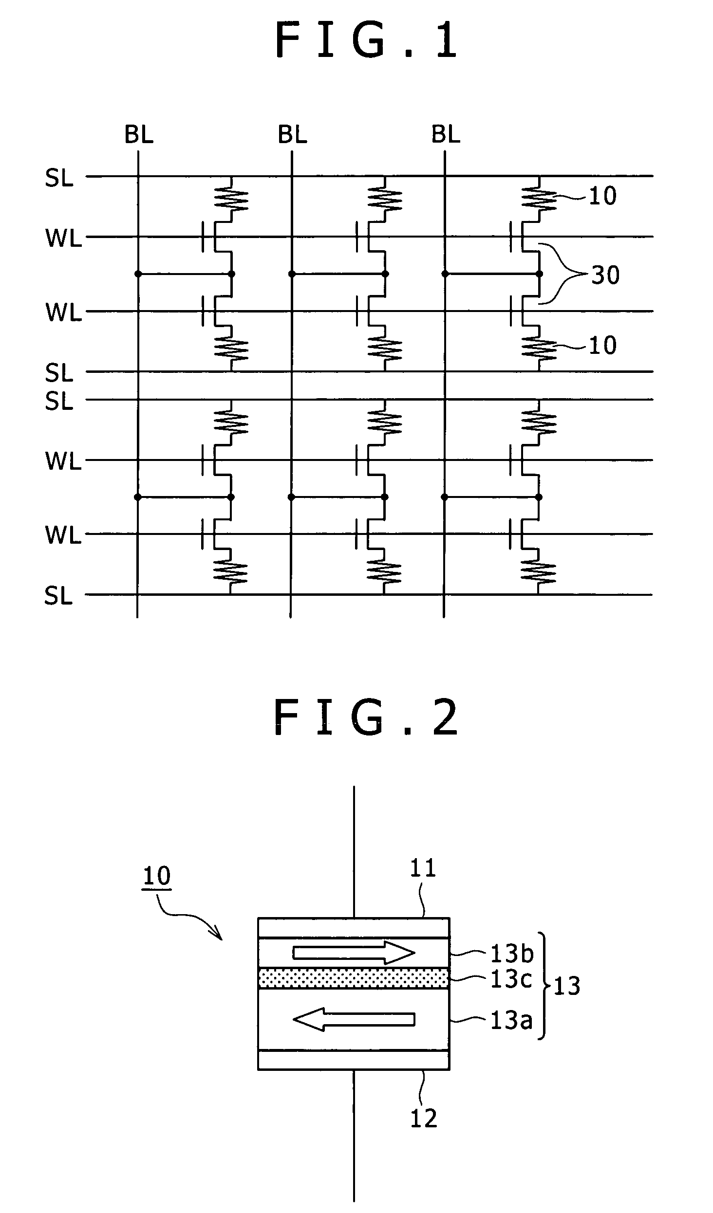
[0025]A first embodiment of a storage apparatus according to the present invention will first be described. Description in this case will be made by taking a device that stores information using spin injection magnetization reversal as an example of a variable resistance element.

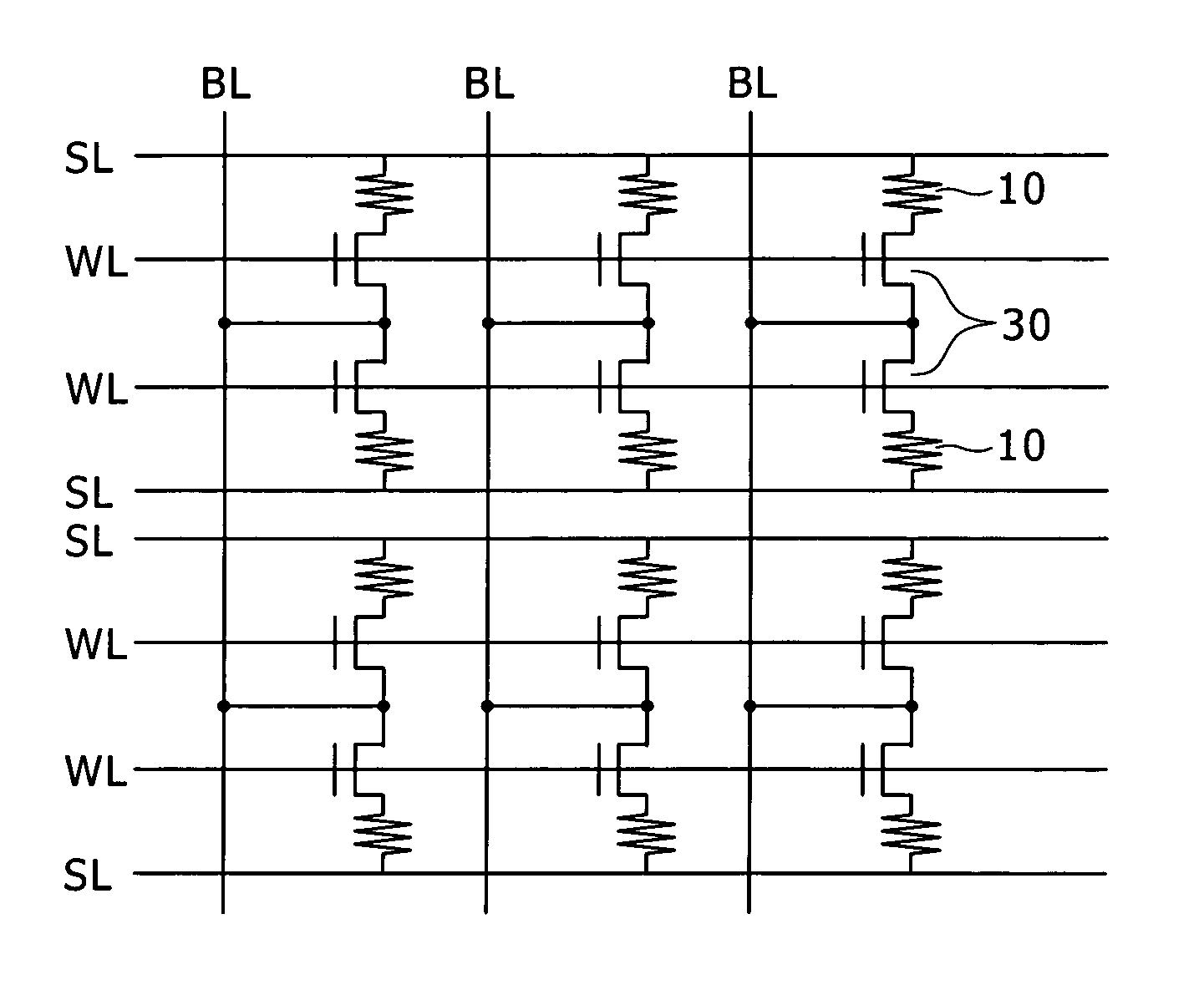
[0026]FIG. 1 is a circuit diagram schematically showing an example of configuration of the storage apparatus according to the first embodiment of the present invention.

[0027]As illustrated in the figure, the storage apparatus described in the first embodiment has a plurality of variable resistance elements 10 arranged in the form of a matrix. The storage apparatus further includes a selecting transistor 30 in such a manner as to correspond to each variable resistance element 10, the selecting transistor 30 functioning as an element for controlling the variable resistance element 10. A bit line BL as a data signal line is disposed in each column in the matrix. A source line SL as a common line and a word line...

second embodiment

[0059]A second embodiment of a storage apparatus according to the present invention will next be described. Description in the following will be made by taking as an example a case where variable resistance elements store information using mobile ions. However, description will be made mainly of differences from the foregoing first embodiment, and description of the same points will be omitted.

[0060]The storage apparatus described in the second embodiment has variable resistance elements different from those of the first embodiment.

[0061]FIG. 7 is a diagram of assistance in explaining an example of general structure of a variable resistance element.

[0062]As illustrated in the figure, the variable resistance element 20 described in the second embodiment has a recording layer 23 between two electrodes 21 and 22. The recording layer 23 includes an ion source layer 23a and a high-resistance film 23b.

[0063]The ion source layer 23 a includes one or more kinds of element (metallic element...


PUM


Abstract

The present invention provides a storage apparatus including a variable resistance element having a recording layer between two electrodes. In the variable resistance element, a resistance value of the recording layer is reversibly changed to one of a value in a high-resistance state and a value in a low-resistance state by applying potentials of different polarities to the two electrodes. An absolute value of a threshold value of an applied signal at a time of change from the high-resistance state to the low-resistance state and an absolute value of a threshold value of an applied signal at a time of change from the low-resistance state to the high-resistance state differ from each other. A reading signal for detecting the resistance value of the recording layer in the variable resistance element is applied with a polarity of one of the threshold values of the applied signals which one has a higher absolute value and with a value lower than the absolute value.

Description

CROSS REFERENCES TO RELATED APPLICATIONS[0001]The present invention contains subject matter related to Japanese Patent Application JP 2004-295502 filed in the Japanese Patent Office on Oct. 8, 2004, the entire contents of which being incorporated herein by reference.BACKGROUND OF THE INVENTION[0002]The present invention relates to a storage apparatus that has a variable resistance element in which the resistance value of a recording layer is changed reversibly by applying potentials of different polarities to two electrodes, and which stores information using a change in resistance of the variable resistance element.[0003]Recently, with the dramatic spread of information communication devices, portable terminal devices and the like, higher performance such as a higher degree of integration, higher speed, lower power consumption and the like is required of elements such as a memory, a logic and the like forming these devices. Of such elements, nonvolatile memories, in particular, are...

Claims


Application Information

Patent Timeline
Patent Type & Authority Patents(United States)
IPC IPC(8): G11C11/00
CPCG11C11/16
Inventor OOTSUKA, WATARUTSUSHIMA, TOMOHITOHACHINO, HIDENARI
Owner SONY SEMICON SOLUTIONS CORP
Why Eureka
Try Eureka