Switchable vortex generator and array formed therewith, and uses of the same

a vortex generator and array technology, applied in the field of vortex generators, can solve the problems of affecting the accuracy the time required for re-rigging and removing the vortex generator, and the disturbance of the vortex generator, so as to achieve the effect of more precise measurement results

Active Publication Date: 2013-12-31
AIRBUS OPERATIONS GMBH
View PDF30 Cites 7 Cited by
  • Summary
  • Abstract
  • Description
  • Claims
  • Application Information

AI Technical Summary

Benefits of technology

[0012]It is an object of the present invention to provide a vortex generator with which the development of new vehicle and airplane configurations can be made substantially quicker and simpler.
[0013]It is a further object to provide an optimized equipment and method for easy and quick aerodynamic and / or acoustic measurements on all kinds of vehicles.
[0014]It is a further object to provide an optimized vortex generator that can be easily adapted to special needs without wasting energy.

Problems solved by technology

If the aerodynamics, rather than the acoustics of the configuration to be tested are to be measured in the wind tunnel, vortex generators are a disturbance.
A main drawback is the re-rigging time needed to repeatedly apply and remove the vortex generators.
A lot of time is thus lost which could otherwise be used for measuring.

Method used


Image

  • Switchable vortex generator and array formed therewith, and uses of the same
  • Switchable vortex generator and array formed therewith, and uses of the same
  • Switchable vortex generator and array formed therewith, and uses of the same

Examples


Embodiment Construction

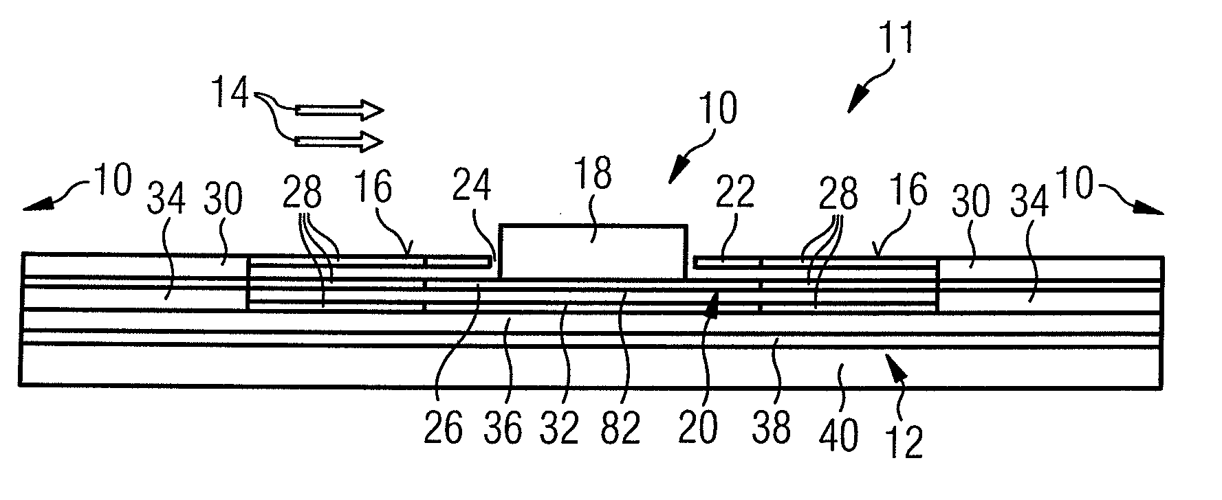
[0056]First, a general structure of a switchable vortex generator generally indicated by 10 will be described with reference to FIG. 1. FIG. 1 shows the area near the surface of a body in a flowing fluid medium, which in the present example is an airplane model 12 to be tested in a wind tunnel (not shown). Airplane model 12, on its surface 16, has an array of vortex generators 10, of which only one is shown in detail, against which a wind tunnel flow 14 flows. Neighboring identically structured vortex generators 10 are indicated by reference numerals 10 left and right of the structure shown. The array forms a vortex generating apparatus 11 having a plurality of commonly switchable vortex generators 10.

[0057]Vortex generator 10 has a vortex generating element 18, which is movable between a first position—extended state—and a second position—retracted state by means of a supporting means 20.

[0058]Vortex generator 10 has a covering membrane 22 for providing a surface 16 which is as smo...


PUM


Abstract

The invention relates to a vortex generator (10), in particular for a model (12) in a fluid-dynamic channel. In order to save time during the development of vehicles, in particular aircraft, in particular to save wind tunnel time, it is suggested to configure the vortex generator (10) switchable. Further, the invention relates to various uses of such a switchable vortex generator (10), in particular on models in fluid-dynamic channels and in fluid-dynamic channel tests.

Description

CROSS-REFERENCE TO RELATED APPLICATIONS[0001]This application claims priority to German Patent Application No. 10 2008 022 504.5 filed on May 7, 2009. The entire disclosure of German Patent Application No. 10 2008 022 504.5 is hereby incorporated herein by reference.BACKGROUND OF THE INVENTION[0002]1. Field of the Invention[0003]The invention relates to a vortex generator and various uses of the same.[0004]2. Background Information[0005]A vortex generator (also referred to as a turbulator or turbulence generator), in the field of aerodynamics, refers to a small artificially applied surface discontinuity, which is supposed to generate a vortex in a fluid medium flowing over a surface. For example, a vortex generator is used to prevent stalling from happening in a controlled manner. Vortex generators can be found, for example, on the top surfaces of the wings of airplanes. An example of an array of vortex generators on a wing profile is explained in more detail in WO 00 / 15961.[0006]Vo...

Claims


Application Information

Patent Timeline
Patent Type & Authority Patents(United States)
IPC IPC(8): B64C21/00B64C5/10B64C9/00B64C19/00B64C3/38
CPCG01M9/04F15D1/12B64C3/38B64C23/06Y02T50/10
Inventor NEITZKE, KLAUS-PETERBAUER, KARINBOLZMACHER, CHRISTIANKUPKE, WINFRIED
Owner AIRBUS OPERATIONS GMBH
Why Eureka
Try Eureka