Switchable Vortex Generator and Array Formed Therewith, and Uses of the Same

Active Publication Date: 2010-01-28
AIRBUS OPERATIONS GMBH
View PDF20 Cites 56 Cited by
  • Summary
  • Abstract
  • Description
  • Claims
  • Application Information

AI Technical Summary

Benefits of technology

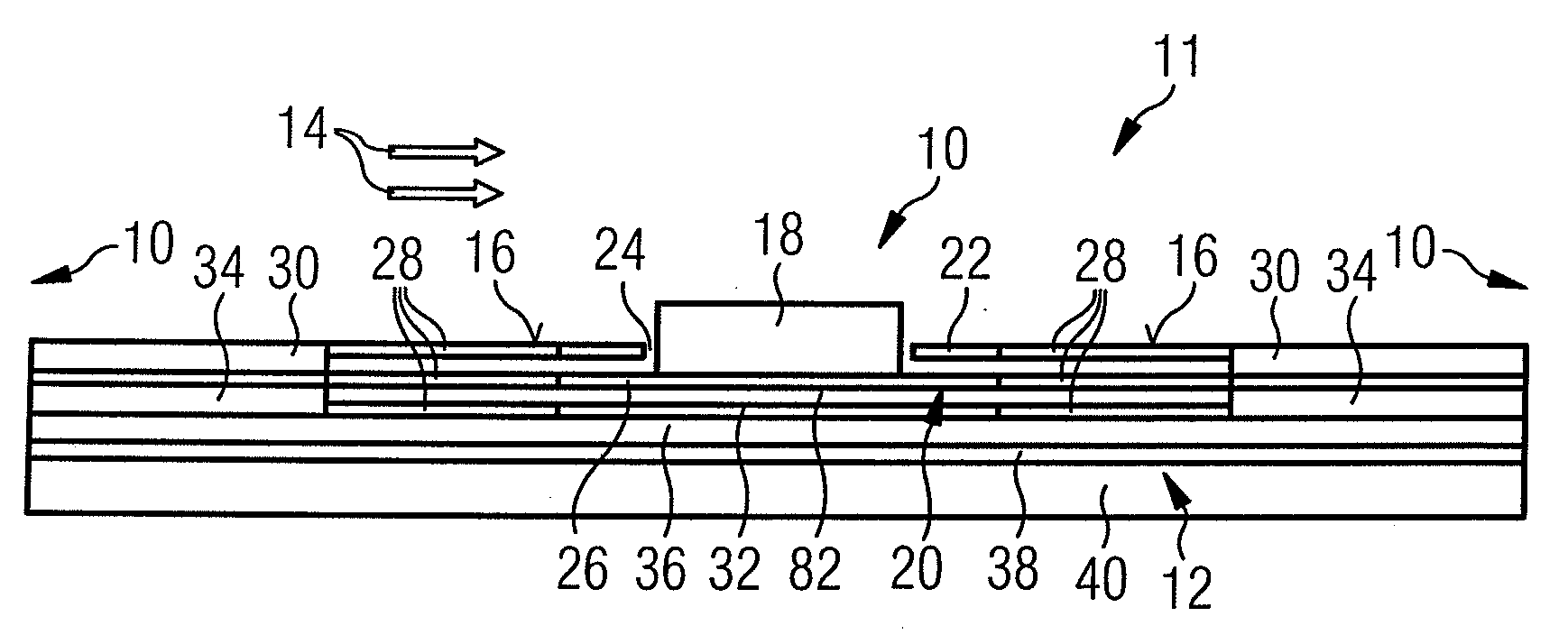
[0041]In wind tunnel tests, bodies in flowing fluid media can be used which are provided with such switchable vortex generators. Switching the vortex generators on and off can be done while the wind tunnel is operating. This is how both aerod

Problems solved by technology

If the aerodynamics, rather than the acoustics of the configuration to be tested are to be measured in the wind tunnel, vortex generators are a disturbance.
A main

Method used


Image

  • Switchable Vortex Generator and Array Formed Therewith, and Uses of the Same
  • Switchable Vortex Generator and Array Formed Therewith, and Uses of the Same
  • Switchable Vortex Generator and Array Formed Therewith, and Uses of the Same

Examples


Example

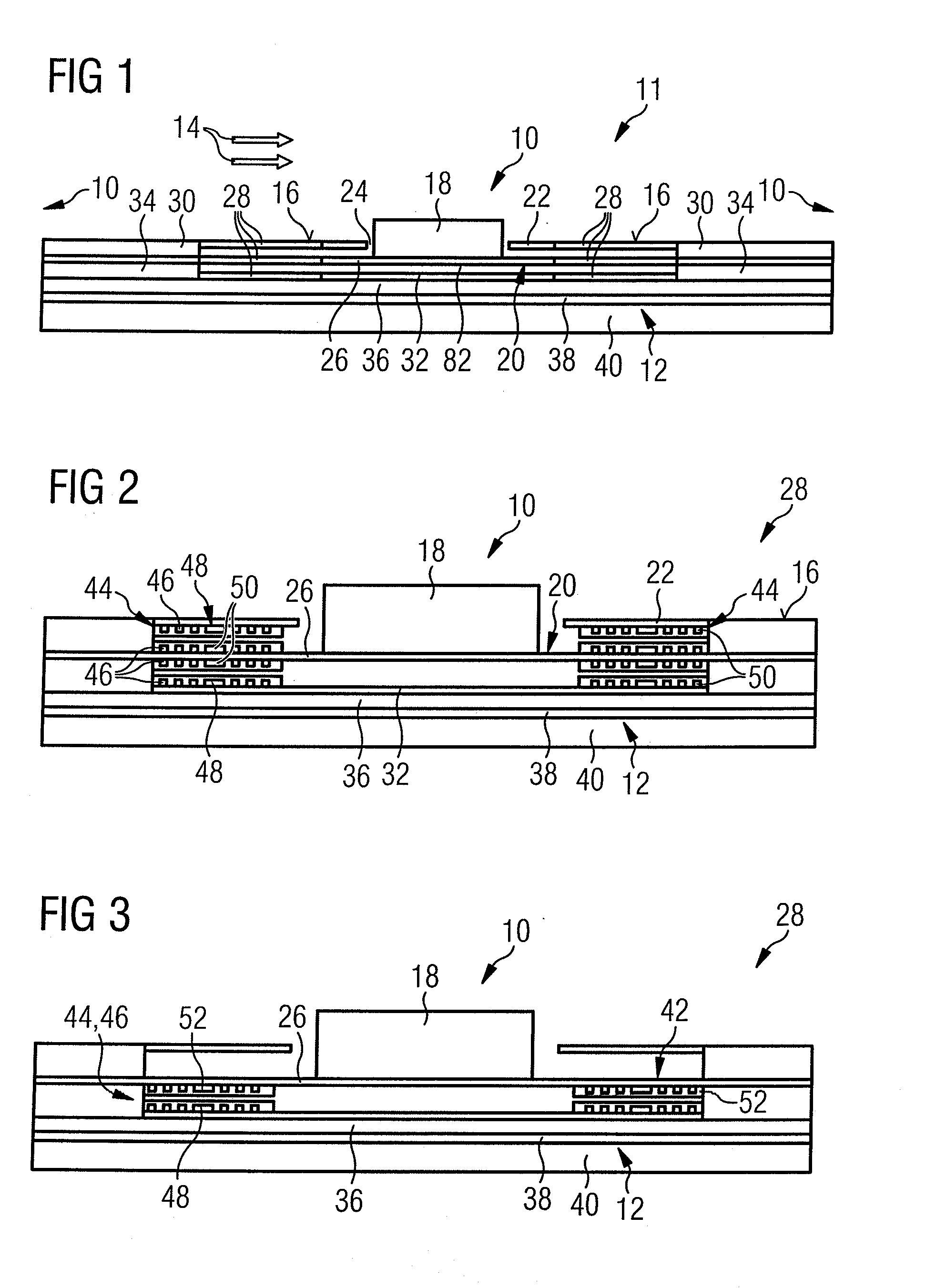
[0064]The first embodiment according to FIG. 2 shows a structure possible for a bistable state. The most variable switching ability is provided by an electromagnetic drive with inserted magnetically active layers. The structure of the planar coils 46 and also the vortex generator 10 overall, and in particular of the vortex generating element 18 can advantageously be realized in MEMS technology.

[0065]However, not all of the elements of the electromagnetic drive shown in FIG. 2 need to be implemented. FIG. 3 shows a second embodiment of the vortex generator in a reduced form, wherein the coil systems 44 are only present on one side of actuator membrane 26. This structure is less cumbersome, but the switching forces achievable are smaller. Without current flow, actuator membrane 26 with vortex generating element 18 is in a resting position. A current through the planar coils 46 in a suitable direction leads to an attraction between the planar coils 46 until the permanent-magnetic core ...

Example

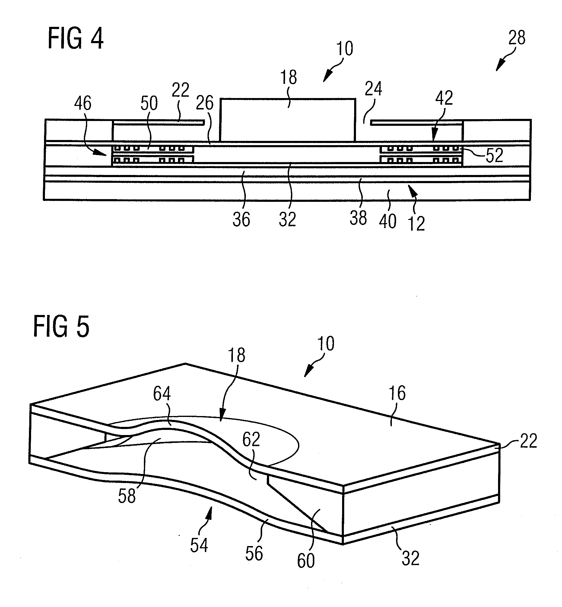
[0069]FIG. 5 shows a concrete fourth embodiment of vortex generator 10 with a lift-reinforcing piezo-electric drive 54. This embodiment of the vortex generator 10 has a large piezo membrane 56 at the bottom of a cavity 58 filled with liquid. The boundary surfaces 60 of cavity 58 leave an opening 62 smaller with respect to the surface of piezo membrane 56 at the top, which is closed off by a flexible area of covering membrane 64. By directly transmitting the volume change initiated by means of piezo membrane 56, a lift-reinforcement on the flexible area 64 of the covering membrane is achievable by the fluid. Piezo membrane 56 can also have a bistable configuration, wherein two predefined states can be selected: vortex generator ON or OFF. Piezo material is used for switching.

[0070]Two modifications of an embodiment of the switchable vortex generator 10 with a piezo-electric drive are shown in FIG. 6, but without lift reinforcement. For creating this un-reinforced piezo-electric drive...


PUM


Abstract

The invention relates to a vortex generator (10), in particular for a model (12) in a fluid-dynamic channel. In order to save time during the development of vehicles, in particular aircraft, in particular to save wind tunnel time, it is suggested to configure the vortex generator (10) switchable. Further, the invention relates to various uses of such a switchable vortex generator (10), in particular on models in fluid-dynamic channels and in fluid-dynamic channel tests.

Description

CROSS-REFERENCE TO RELATED APPLICATIONS[0001]This application claims priority to German Patent Application No. 10 2008 022 504.5 filed on May 7, 2009. The entire disclosure of German Patent Application No. 10 2008 022 504.5 is hereby incorporated herein by reference.BACKGROUND OF THE INVENTION[0002]1. Field of the Invention[0003]The invention relates to a vortex generator and various uses of the same.[0004]2. Background Information[0005]A vortex generator (also referred to as a turbulator or turbulence generator), in the field of aerodynamics, refers to a small artificially applied surface discontinuity, which is supposed to generate a vortex in a fluid medium flowing over a surface. For example, a vortex generator is used to prevent stalling from happening in a controlled manner. Vortex generators can be found, for example, on the top surfaces of the wings of airplanes. An example of an array of vortex generators on a wing profile is explained in more detail in WO 00 / 15961.[0006]Vo...

Claims


Application Information

Patent Timeline
IPC IPC(8): G01F1/32
CPCF15D1/12B64C3/38G01M9/04B64C23/06Y02T50/10
Inventor NEITZKE, KLAUS- PETERBAUER, KARINBOLZMACHER, CHRISTIANKUPKE, WINFRIED
Owner AIRBUS OPERATIONS GMBH
Why Eureka
Try Eureka