Electric machine

a technology of electric machines and electric motors, applied in the direction of dynamo-electric machines, magnetic circuit rotating parts, magnetic circuit shapes/forms/construction, etc., can solve the problems of significant reduction of mechanical load capacity and flux loss, and achieve the effect of minimizing flux loss

Inactive Publication Date: 2014-05-20
ROBERT BOSCH GMBH
View PDF14 Cites 12 Cited by
  • Summary
  • Abstract
  • Description
  • Claims
  • Application Information

AI Technical Summary

Benefits of technology

[0004]The electrical machine according to the invention has the advantage that an embodiment is improved with respect to magnetic flux losses and mechanical load capacity. In particular, magnetic flux losses for a predetermined mechanical load capacity can be reduced, or a mechanical load capacity can be improved for predetermined magnetic flux losses.

Problems solved by technology

The electric motor which is known from US 2007 / 0252469 A1 has the disadvantage that flux losses occur via the laminates, or the mechanical load capacity is considerably reduced, depending on the configuration.

Method used


Image

  • Electric machine
  • Electric machine
  • Electric machine

Examples


Embodiment Construction

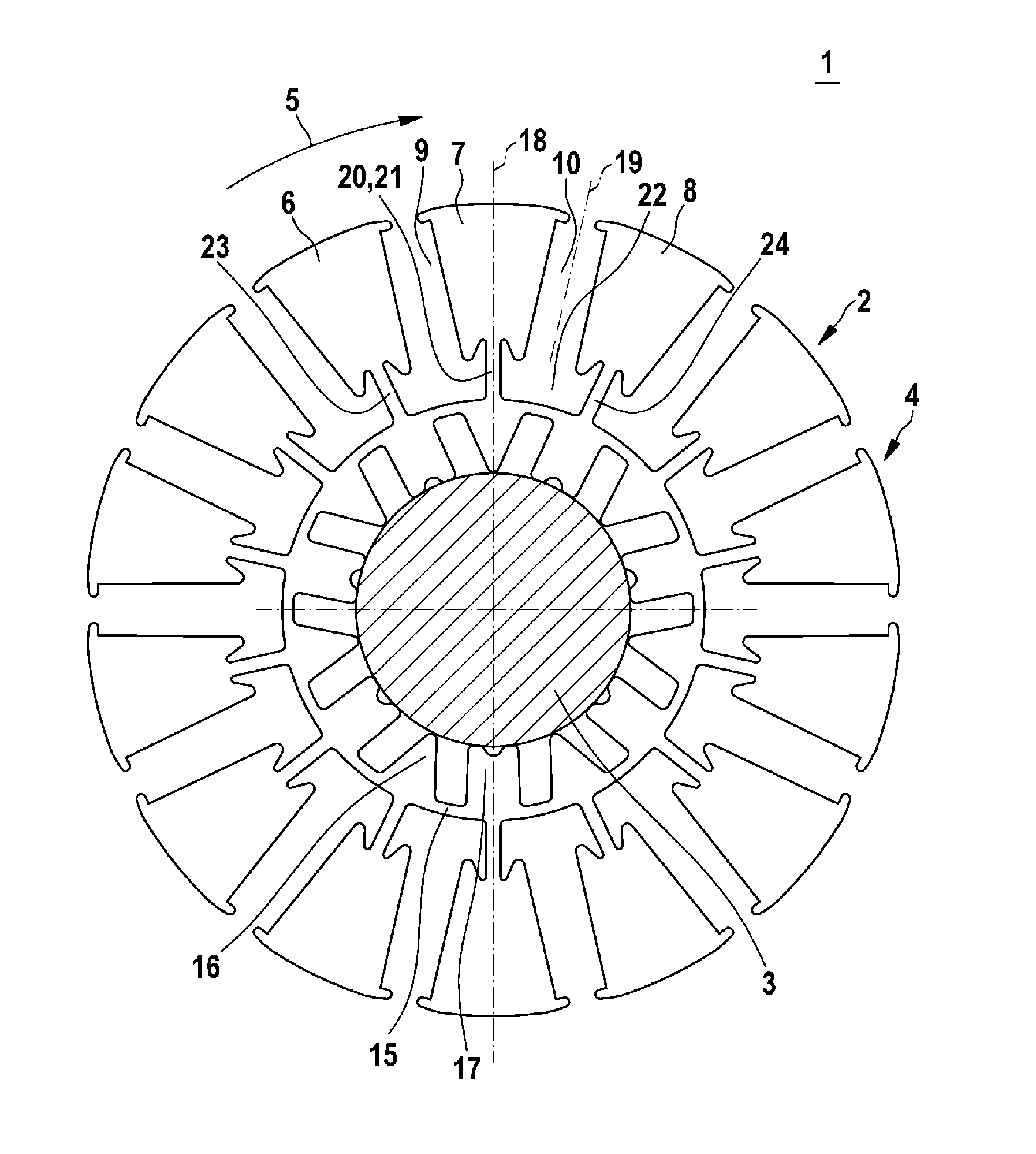
[0020]FIG. 1 shows an electrical machine 1 having a rotor 2 and a shaft 3, in the form of a schematic illustration corresponding to one exemplary embodiment. In particular, the electrical machine 1 may be in the form of an electric motor and may be used for a motor vehicle. Specifically, the electrical machine 1 is suitable for movement operated by external power of elements of a motor vehicle, for example a sliding roof, a window or a seat element. Furthermore, the electrical machine 1 can be used as an electric motor for steering power assistance. The electrical machine 1 according to the invention is, however, also suitable for other applications.

[0021]The electrical machine 1 is preferably in the form of a permanent-magnet electrical drive, in which case the rotor 2 may be configured in the form of spokes or as a collector. In this exemplary embodiment, the rotor 2 has a laminate 4 and a multiplicity of further laminates which correspond to the laminate 4. The laminate 4 is in t...


PUM


Abstract

An electric machine (1), particularly used as an electric motor, has a rotor (2) comprising a plurality of disks (4). A disk (4) of the rotor (2) is divided in a circumferential direction (5) into a plurality of disk sectors (6, 7, 8) between which magnetic pockets (9, 10) are designed. Furthermore, the disk (4) has an inner fastening collar (15) and connecting members (20, 23, 24) connecting the disk sectors (6, 7, 8) to the fastening collar (15). Such a connecting member (20) comprises a main web (21), a side arm (30) branching off the main rib (21) in the circumferential direction (5), and a side arm (31) branching off the main web (21) opposite to the circumferential direction (5). High mechanical stability of the disk (4) can thus be ensured, wherein magnetic flow losses are reduced.

Description

BACKGROUND OF THE INVENTION[0001]The invention relates to an electrical machine, in particular an electric motor having a rotor and a shaft. In particular, the invention relates to the field of electric motors for motor vehicles, in particular electric motors which are used as electrical auxiliary drives for movement, operated by external power, or for assistance to movement, of elements of a motor vehicle.[0002]US 2007 / 0252469 A1 discloses an electric motor having laminates, with magnets being provided in cutouts which extend through the rotor core in the axial direction. These cutouts also have a radial extent. The configuration of the rotor reduces the magnetic flux losses as much as possible.[0003]The electric motor which is known from US 2007 / 0252469 A1 has the disadvantage that flux losses occur via the laminates, or the mechanical load capacity is considerably reduced, depending on the configuration.SUMMARY OF THE INVENTION[0004]The electrical machine according to the inventi...

Claims


Application Information

Patent Timeline
Patent Type & Authority Patents(United States)
IPC IPC(8): H02K1/06
CPCH02K1/2773H02K1/30
Inventor FEUERROHR, LINROTH, KARL-JUERGENKOENIG, TILOHOLZWARTH, BRUNO
Owner ROBERT BOSCH GMBH
Why Eureka
Try Eureka