
Micro-optic security device

a security device and micro-optic technology, applied in the field of micro-optic security devices, can solve the problems of limited number and complexity of image transformations, and achieve the effect of more resistance to counterfeiting

Active Publication Date: 2014-06-03
CRANE SECURITY TECH
View PDF35 Cites 28 Cited by
  • Summary
  • Abstract
  • Description
  • Claims
  • Application Information

AI Technical Summary

Benefits of technology

[0003]Optical materials have long been recognized as valued additions to security threads used in banknotes. These materials allow for a variety of self-authenticating optical effects while rendering the security thread and thus the banknote more resistant to counterfeiting.

Problems solved by technology

While the abruptness of the change is softened by the use of a transition zone, the extent to which the smoothness of synthetic image transformations can be improved, as well as the number and complexity of these image transformations is limited where only two intact icons are involved in each transformation and where the transformations do not occur continuously but rather only during a portion of the time in which the film structure is rotated or viewpoints changed.

Method used


Image

  • Micro-optic security device
  • Micro-optic security device
  • Micro-optic security device

Examples


Embodiment Construction

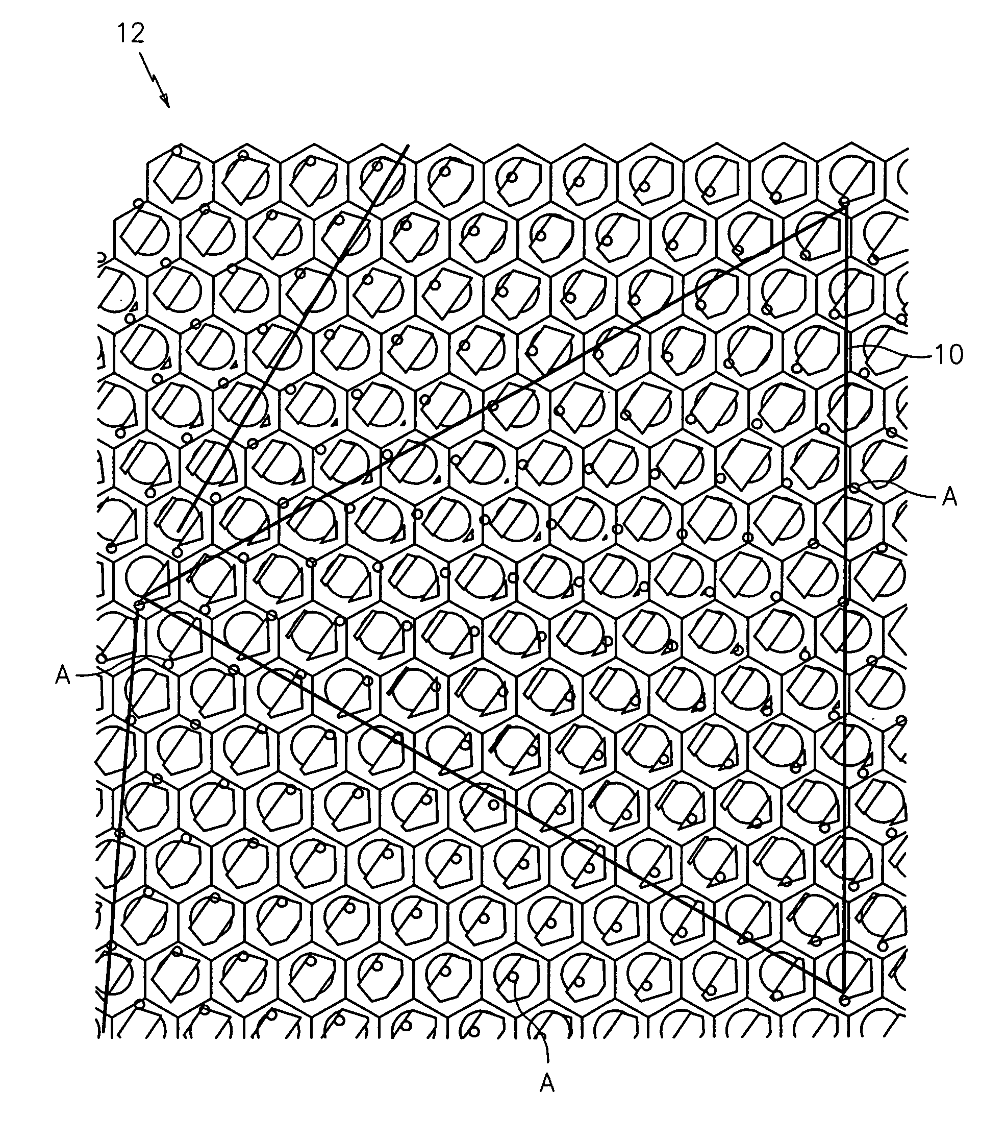
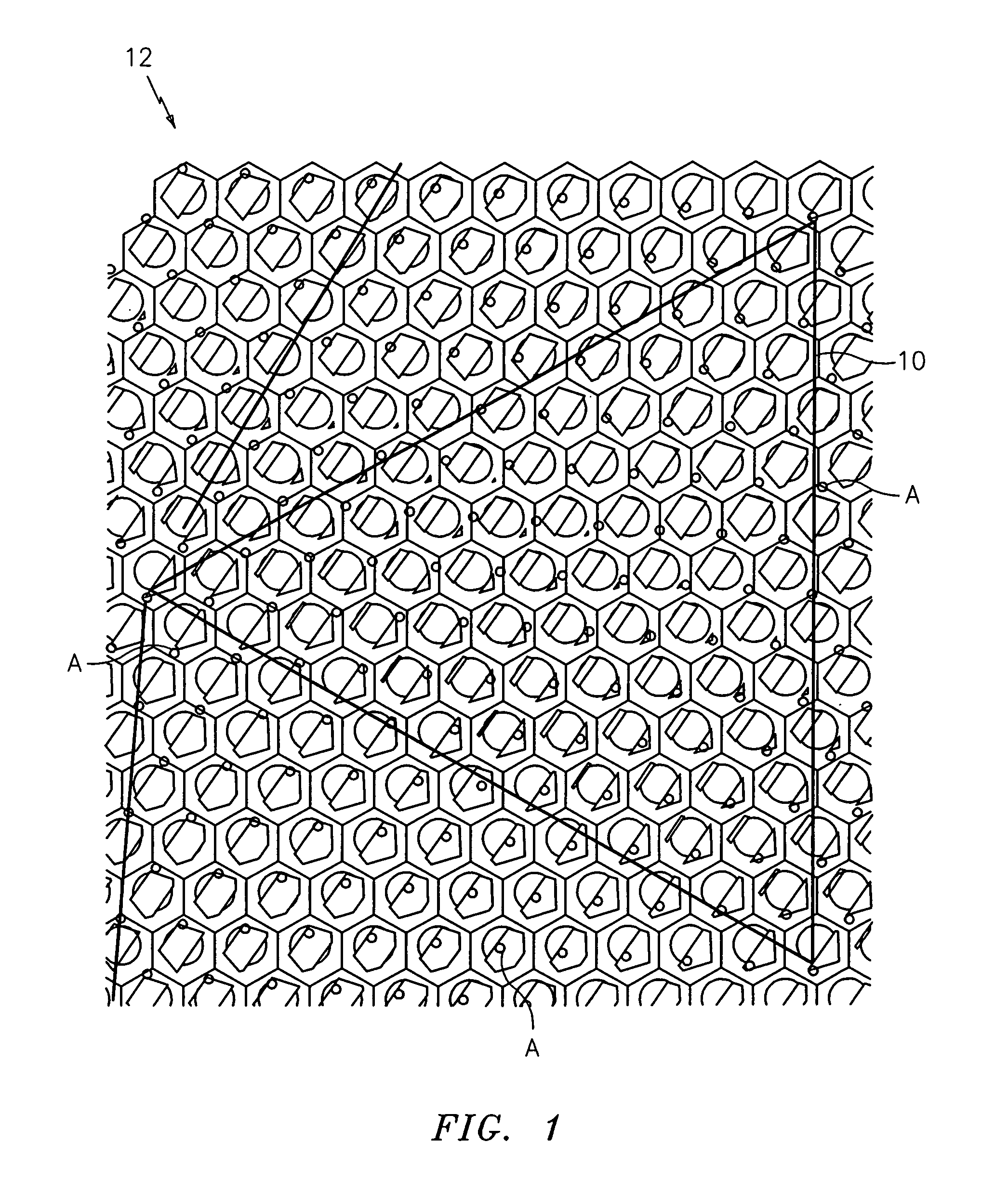
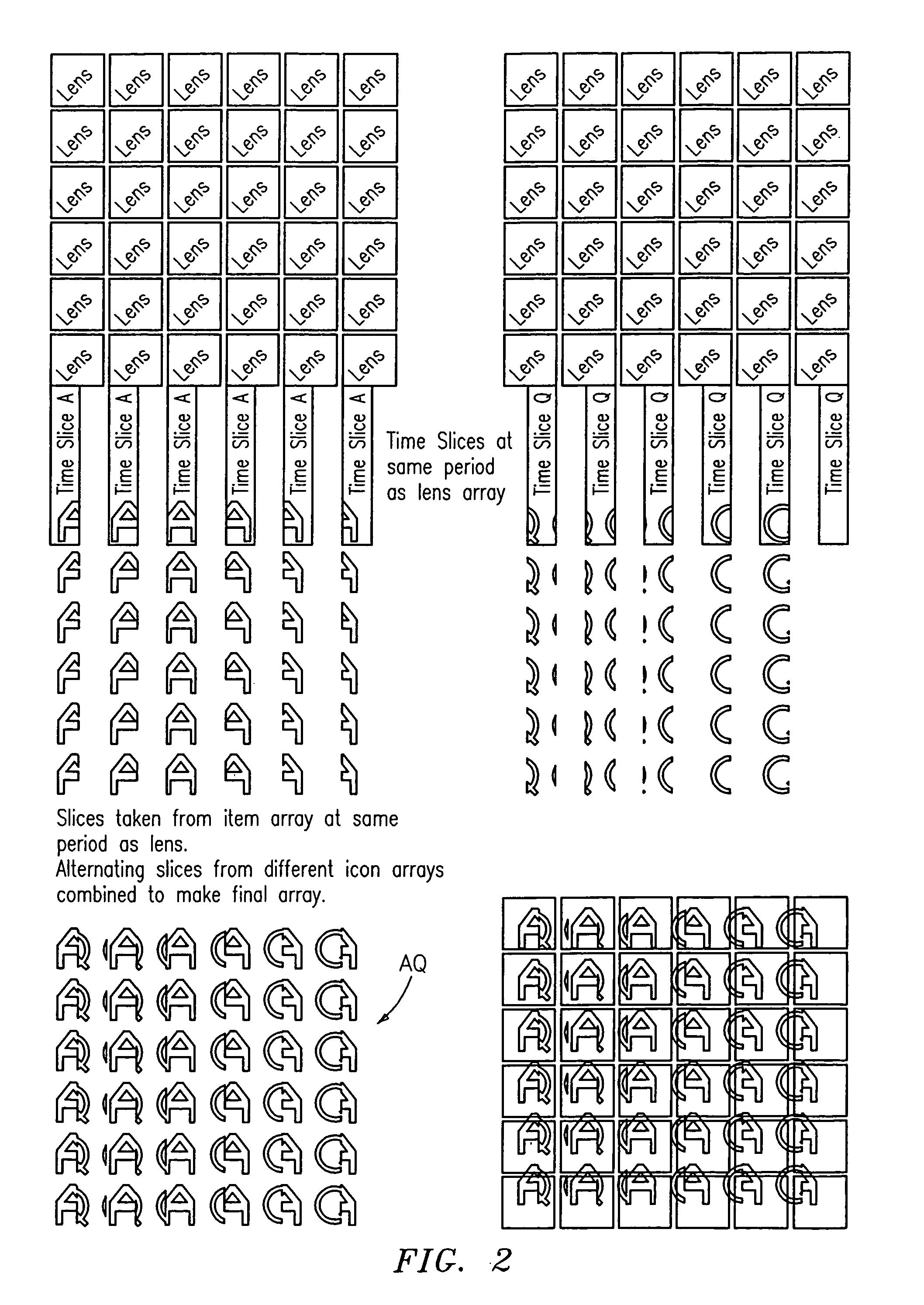
[0038]By way of the present invention, it has been discovered that the use of stitched icons composed of adjacent or interleaved slices in a micro-optic security device can greatly expand the number and complexity of the visual effects offered by such devices. It has also been discovered that the configuration or arrangement of slices in a stitched icon plays a role in the number of synthetic images that may be projected at any one viewing angle by the device. In particular, it has been discovered that abutting or slightly overlapping slices allow the device to simultaneously project two or more synthetically magnified images that may be separated or linked, thereby greatly increasing the complexity of these images.

[0039]The micro-optic security device of the present invention may be utilized in a variety of different forms with any document (e.g., banknote, passport, identity card, credit card), label, means of identification, commercial product (e.g., optical disks, CDs, DVDs, pac...


PUM


Abstract

A micro-optic security device that employs one or more planar arrangements of stitched icons and that projects at any given viewing angle one or more synthetically magnified images, is provided. The synthetically magnified image(s) constitutes either a single or multipart image(s) that optionally changes to a different image(s) as the security device is tilted, or as the viewing angle changes.

Description

RELATED APPLICATION[0001]This application claims benefit of and priority to U.S. Provisional Patent Application Ser. No. 60 / 953,304 filed Aug. 1, 2007, which is incorporated herein by reference in its entirely.TECHNICAL FIELD[0002]The present invention generally relates to a micro-optic security device for projecting images, and more specifically relates to a micro-optic security device that employs one or more planar arrangements of stitched icons and that projects at any given viewing angle one or more synthetically magnified images. The synthetically magnified image(s) constitutes either a single or multipart image(s) that optionally changes to a different image(s) as the security device is tilted, or as the viewing angle changes.BACKGROUND AND SUMMARY OF THE INVENTION[0003]Optical materials have long been recognized as valued additions to security threads used in banknotes. These materials allow for a variety of self-authenticating optical effects while rendering the security th...

Claims


Application Information

Patent Timeline
Patent Type & Authority Patents(United States)
IPC IPC(8): D05B93/00
CPCB42D25/355B42D15/0026G02B3/0006G02B27/022B42D2035/44B42D2035/20B42D25/29B42D25/45B42D25/324B42D25/351B42D25/342G02B27/06B44F1/10D05B93/00
Inventor COTE, PAUL, F.
Owner CRANE SECURITY TECH
Learn More