Filter holder used for smoking, a smoking pipe, and a smoking pipe unit

a filter holder and smoking pipe technology, which is applied in the field of filter holder used for smoking, smoking pipe and smoking pipe unit, can solve the problems of undesirable reduction of mainstream smoke, tar amount in mainstream smoke sent into the smoker's mouth, and inability to reduce the vapor phase components of mainstream smoke, so as to prevent the generation of flavor components and ensure the original absorption performance of the filter

Inactive Publication Date: 2014-07-15
JAPAN TOBACCO INC
View PDF27 Cites 12 Cited by
  • Summary
  • Abstract
  • Description
  • Claims
  • Application Information

AI Technical Summary

Benefits of technology

[0011]It is an object of the present invention to provide a filter holder for smoking which is capable of reliably exerting the above-mentioned conventional basic function or an additional function with respect to mainstream smoke during smoking, a smoking pipe and a smoking pipe unit including the filter holder, respectively.

Problems solved by technology

However, the filter of the smoking pipe of Document 1 is not capable of reducing vapor-phase components (acetaldehyde, acetone, benzene, etc.) and gas-phase components (CO, NO, etc.) which are contained in the mainstream smoke.
In the case of the dilution-type filter cigarette and smoking pipe, when a dilution rate of the mainstream smoke is excessively high, a tar amount in the mainstream smoke which is sent into the smoker's mouth, that is, a nicotine amount in the tar, is undesirably reduced.
As a result, the smoker cannot enjoy the original flavor and taste of the cigarette.
When the perforation line is located in the end portion of the tip paper regardless of this requirement, glue is applied onto the inner surface of the end portion except for the perforation line, and it is impossible to secure an adequate glue-applied area.
As a result, bond strength between the filter and the cigarette is low, and it is then practically difficult to form the perforation line in the end portion of the tip paper.
However, according to Documents 2 and 3, there is the possibility that the perforation line would be partially blocked by smoker's fingers during smoking.
When the perforation line is blocked even partially, air intake into the filter becomes insufficient, and mainstream smoke is not diluted as desired.

Method used


Image

  • Filter holder used for smoking, a smoking pipe, and a smoking pipe unit
  • Filter holder used for smoking, a smoking pipe, and a smoking pipe unit
  • Filter holder used for smoking, a smoking pipe, and a smoking pipe unit

Examples


first embodiment

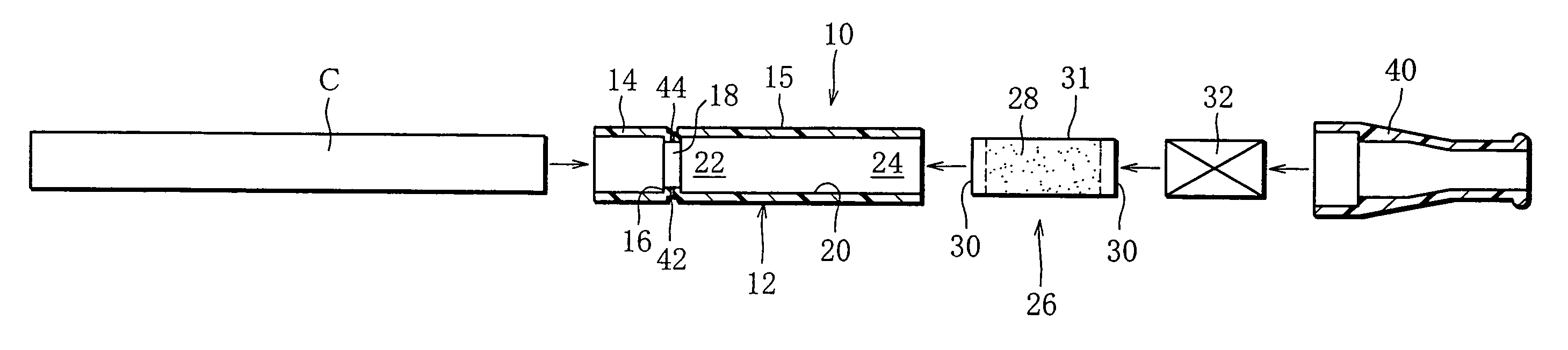
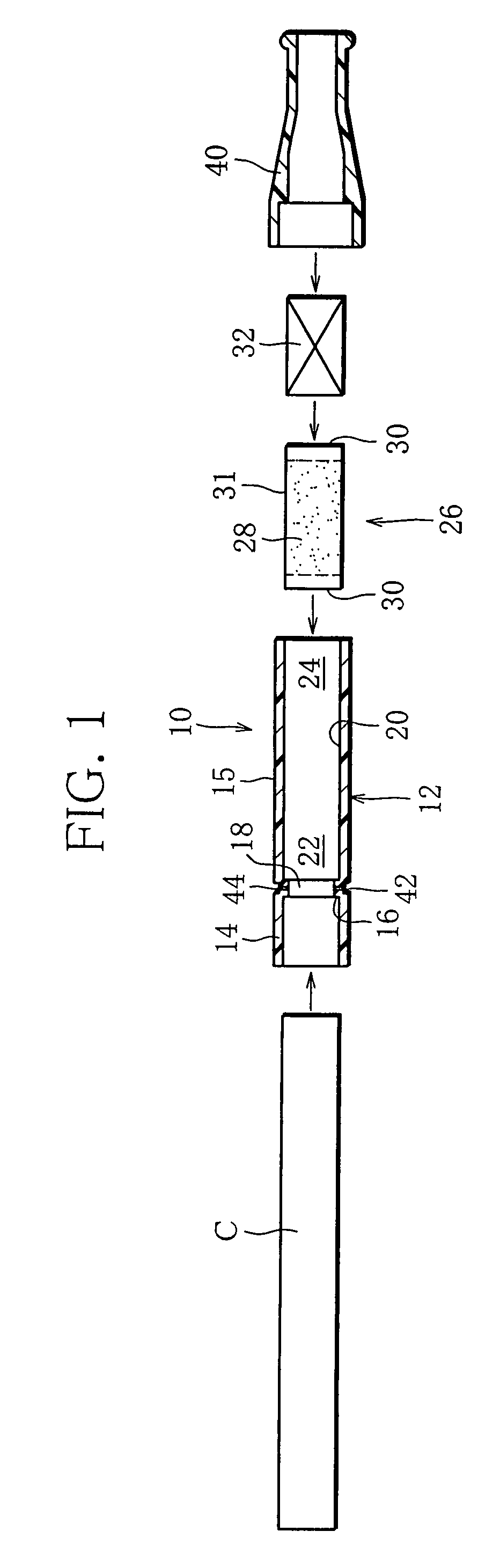
[0064]A smoking pipe of a first embodiment which is shown in FIG. 1 comprises a filter holder 10. The filter holder 10 includes a hollow cylinder, namely a tubular body 12, which is made of synthetic resin. The tubular body 12 has an open end in each end thereof.

[0065]One end portion and the other end portion of the tubular body 12 are formed as a socket portion 14 and a loading portion 15, respectively. The socket portion 14 and the loading portion 15 are separated from each other by an annular partition 16 located in the tubular body 12. The annular partition 16 is protruding from an inner circumferential surface of the tubular body 12. Accordingly, the partition 16 has a smaller internal diameter than the socket portion 14. The socket portion 14 has an internal diameter that is slightly larger than an external diameter of a rod-shaped smoking article C. Therefore, the rod-shaped smoking article C is insertable into the socket portion 14 until contacting the annular partition 16. ...

second embodiment

[0107]FIG. 13 shows the filter holder 10 of a

[0108]The filter holder 10 of FIG. 13 has an annular groove 42 that is so arranged as to surround the upstream end of a filter-containing chamber 22. A plurality of vent holes 44 are formed in a bottom of the annular groove 42. In this case, outside air is introduced from the vent holes 44 through the wrapping paper into an upstream end of a charcoal filter 26 and dilutes the mainstream smoke from the cigarette during smoking.

third embodiment

[0109]FIG. 14 shows a part of a filter holder of a

[0110]The filter holder 10 of the third embodiment further includes an adjust ring 46. The adjust ring 46 is made of synthetic resin and embedded in the annular groove 42 of the tubular body 12. The adjust ring 46 rotates in the circumferential direction of the tubular body 12 and has a plurality of slots 48 corresponding to the vent holes 44 of the annular groove 42. The slots 48 extend in a circumferential direction of the adjust ring 46, and have such length that the slots 48 are not completely blocked by the smoker's fingers during smoking. By carrying out a rotating operation, the adjust ring 46 is capable of fully opening / closing the vent holes 44 or of adjusting the opening of the vent holes 44. An upper half of FIG. 14 shows a state in which the vent hole 44 is opened through the slot 48 of the adjust ring 46, whereas a lower half of FIG. 14 shows a state in which the vent hole 44 is closed by the adjust ring 46.

[0111]FIG. 15...


PUM


Abstract

A filter holder used for smoking has a tubular body (12), which includes a socket portion (14) for receiving a cigarette (C) at one end thereof, a dilution chamber (18) located adjacently to the socket portion (14) in the inside, a chamber (22) for containing a charcoal filter (26), a chamber (24) for containing a flavor generation element (32), an annular groove (42) formed in the outer circumferential surface of the body (12), and a plurality of vent holes (44) formed in the bottom of the annular groove (42) and introduces outside air into the dilution chamber (18).

Description

[0001]This application is a Continuation of copending PCT International Application No. PCT / JP2006 / 304132 filed on Mar. 3, 2006, which designated the United States, and on which priority is claimed under 35 U.S.C. §120. This application also claims priority under 35 U.S.C. §119(a) on Patent Application No(s). 2005-077095 filed in Japan on Mar. 17, 2005. The entire contents of each of the above documents is hereby incorporated by reference.TECHNICAL FIELD[0002]The present invention relates to a filter holder used for smoking, a smoking pipe and a smoking pipe unit including the filter holder, respectively.BACKGROUND ART[0003]A smoking pipe attachable to one end of a cigarette as a rod-shaped smoking article is disclosed, for example, in Unexamined Japanese Utility Model Publication No. 51-65988 (Document 1). The smoking pipe of Document 1 includes a socket portion formed in one end of the pipe and is capable of receiving one end of a cigarette, a mouthpiece formed in the other end, a...

Claims


Application Information

Patent Timeline
Patent Type & Authority Patents(United States)
IPC IPC(8): A24F7/04A24F1/00
CPCA24F13/06A24F13/00
Inventor TARORA, MASAFUMIINAGAKI, MICHIHIRO
Owner JAPAN TOBACCO INC
Why Eureka
Try Eureka