System and process for generation of electrical power

a technology of electrical power generation and process, applied in the direction of steam engine plants, machines/engines, mechanical equipment, etc., can solve the problems of significant quantities of carbon dioxide, the electrical power generation system and process of steam-based thermal to electrical power is relatively inefficient, and the efficiency of nuclear power plants is less than standard fossil fuel plants

Inactive Publication Date: 2014-07-22
SHELL OIL CO
View PDF7 Cites 11 Cited by
  • Summary
  • Abstract
  • Description
  • Claims
  • Application Information

AI Technical Summary

Problems solved by technology

Many of these systems and processes produce significant quantities of carbon dioxide as an undesirable by-product emission.
Electrical power production by steam-based thermal to electrical power systems and processes is relatively inefficient.
Nuclear power plants tend to be less efficient than standard fossil fuel plants, generating electrical power at 30-32% of the heating value of the fuel consumed due to the lower operating temperatures, and consequently lower steam pressures, at which nuclear reactors are run relative to fossil fuel-fired plants.
These specialized systems, equipment, and seals may be impractical in a large scale commercial electrical power plant capable of generating over 100 MW of electrical power.
Substantial power, however, is lost by air cooling the second working fluid because the latent heat of condensation of the second working fluid is rejected to the atmosphere in the air warmed by heat exchange with the second working fluid to condense the second working fluid.
Again, substantial power is lost by air cooling or water cooling the bottoming cycle working fluid because the latent heat of condensation of the bottoming cycle working fluid is rejected to the atmosphere in the air, or lost to the cooling water, warmed by heat exchange with the bottoming cycle working fluid.

Method used


Image

  • System and process for generation of electrical power
  • System and process for generation of electrical power
  • System and process for generation of electrical power

Examples


example 1

Illustrative Example 1

USC CFB Plant with Single Re-Heat Steam Design and Integrated Second Fluid Power Cycle

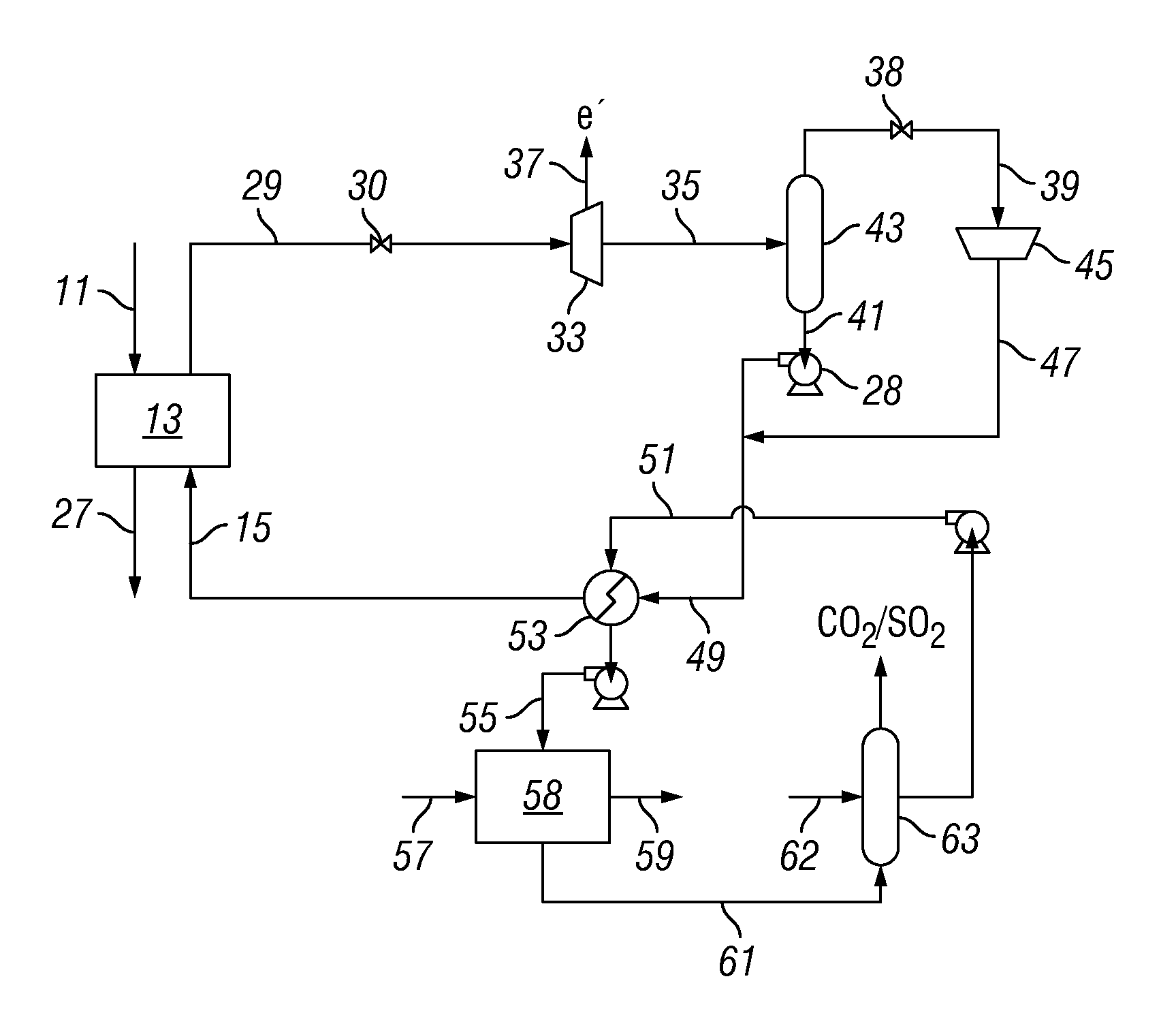
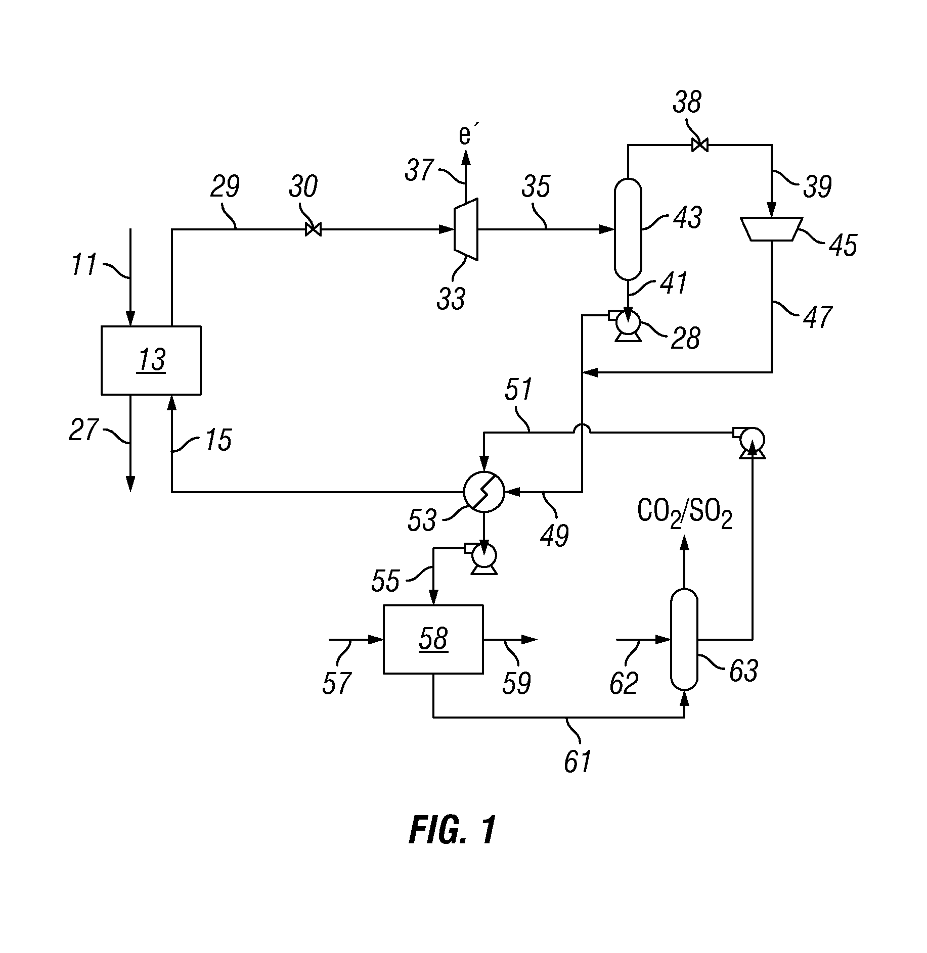
[0133]A design study was prepared based on thermodynamic calculations of a method and system for producing electrical power using a first power cycle utilizing water / steam as a working fluid and a second power cycle utilizing carbon dioxide as a working fluid, where the method and system were in accordance with the present invention. In the first power cycle, a coal-fired heat source was utilized to produce ultra-supercritical steam for generation of electrical power followed by an integrated second fluid power cycle utilizing carbon dioxide as a working fluid.

[0134]In the first power cycle, the coal-fired steam turbine driven generator portion of the design study of Illustrative Example 1 replicated the design study of the USC CFB Plant of nominally 400 MWe capacity described in Comparative Example 1 above with the exception that: (a) the low pressure steam turbine was elimin...

example 2

Illustrative Example 2

USC CFB Plant with Single Re-Heat Steam Design and Integrated Second Fluid Power Cycle Including Power Extraction from Flue Gas

[0166]A design study was prepared based on thermodynamic calculations of a method and a system for producing electrical power using a first power cycle utilizing water / steam as the working fluid and a second power cycle utilizing carbon dioxide as a working fluid, where the method and system were in accordance with the present invention. In the first power cycle, a coal-fired heat source was utilized to produce ultra-supercritical steam for generation of electrical power followed by an integrated second fluid power cycle utilizing carbon dioxide as a working fluid. Power extracted from flue gas produced by burning coal was included in the power produced in the second power cycle.

[0167]In the first power cycle, the coal-fired steam turbine driven generator portion of the design study of Illustrative Example 2 replicated the design study ...

example 3

Illustrative Example 3

USC CFB Plant with Single Re-Heat Steam Design and Integrated Second Fluid Power Cycle including Power Extraction from Flue Gas—Flue Gas Heat Exchanger in Series Flow configuration with Steam / Water Condenser

[0220]In Illustrative Example 3, the design study of Illustrative Example 2 was modified in one respect—the flue gas heat exchanger was placed in a series flow configuration with the steam condenser, where liquid pressurized carbon dioxide having a temperature of from 0 to 10° C. and a pressure of 30 MPa was provided to the flue gas heat exchanger, and the carbon dioxide stream exiting the flue gas heat exchanger was provided to the steam condenser to cool and condense liquid water from the steam provided to the steam condenser. The heated supercritical carbon dioxide exiting the steam condenser was then expanded in the second fluid power cycle. The system and method of the design study prepared in Illustrative Example 3 were in accordance with the system an...


PUM


Abstract

A system and process for generation of electrical power is provided. Electrical power is generated by a system including two integrated power cycles, a first power cycle utilizing water / steam as a working fluid and the second power cycle utilizing a fluid selected from the group consisting of molecular nitrogen, argon, a chemical compound having a boiling point of at most 65° C. at 0.101 MPa and a latent heat of vaporization of at least 350 kJ / kg, and a chemical compound having a boiling point of at most 65° C. at 0.101 MPa and a specific heat capacity as a liquid of at least 1.9 kJ / kg-° K as a working fluid. The working fluid of the second power cycle is expanded through a two-phase expander to produce power in the second power cycle, where the expanded working fluid of the second cycle has a temperature of at most 10° C.

Description

[0001]The present application claims the benefit of U.S. Patent Application No. 61 / 559,855, filed Nov. 15, 2011, the entire disclosure of which is hereby incorporated by reference.BACKGROUND OF THE INVENTION[0002]A large proportion of electrical power generated in the world is produced by systems and processes that transfer thermal power from a heat source to water to produce steam and produce electrical power from the steam. Such systems and processes include fossil fuel power plants including coal-fired power plants, oil-fired power plants, and natural gas-fired power plants; nuclear power plants; geothermal power plants; waste incineration power plants; and solar thermal electric plants. Together these systems and processes for producing electrical power from thermal power account for about 80% of electrical power production worldwide, where coal-fired power plants produce about 41%, natural gas fired power plants produce about 20%, nuclear power plants produce about 15%, and oil...

Claims


Application Information

Patent Timeline
Patent Type & Authority Patents(United States)
IPC IPC(8): F01K25/08F01K23/04
CPCF01K25/08F01K23/04F01K25/10Y02E20/16
Inventor MILAM, STANLEY NEMECTAYLOR, RICHARD BRUCE
Owner SHELL OIL CO
Why Eureka
Try Eureka