Variable oil pump

a variable oil pump and oil pressure technology, which is applied in the direction of positive displacement liquid engines, liquid fuel engines, instruments, etc., can solve the problems of difficult rapid variation of oil pressure, oil pressure, according to engine rpm variation, etc., to improve lubrication effect, simple structure, and rapid ejection

Active Publication Date: 2014-08-19
MEIWA IND CO LTD
View PDF7 Cites 2 Cited by
  • Summary
  • Abstract
  • Description
  • Claims
  • Application Information

AI Technical Summary

Benefits of technology

[0010]In order to solve these problems, the present invention provides a variable oil pump with a simple structure capable of rapidly ejecting a required amount of working fluid using an oil pressure of the working fluid generated according to an engine RPM, and improving a lubrication effect to improve engine efficiency.
[0011]In particular, the present invention also provides a variable oil pump, in which a gap is provided between a plunger and a cylinder to easily operate the plunger using an oil pressure output from an oil pump, capable of more rapidly supplying a required amount of oil using an oil pressure varied according to variation in engine RPM.
[0012]In addition, the present invention also provides a variable oil pump, in which the plunger is perpendicularly operated with respect to a flow direction of the working fluid, capable of operating the plunger in a direction in which a pressure of the working fluid is applied to rapidly and precisely operate the oil pump.

Problems solved by technology

However, since such an oil supply apparatus ejects the working fluid in proportion to the engine RPM regardless of a lubrication state of a portion at which lubrication is needed, fuel efficiency of the engine may be decreased.
In addition, excessive supply of the working fluid at the medium speed and the high speed takes power consumption from the crankshaft, and thus, fuel efficiency of the engine may be decreased.
However, such a structure has the following problem.
Since the valve is configured to be operated according to variation in temperature, it is difficult to rapidly vary the pressure of the oil, i.e., the oil pressure, according to variation in engine RPM.

Method used


Image

  • Variable oil pump
  • Variable oil pump
  • Variable oil pump

Examples


first embodiment

[0033][First Embodiment]

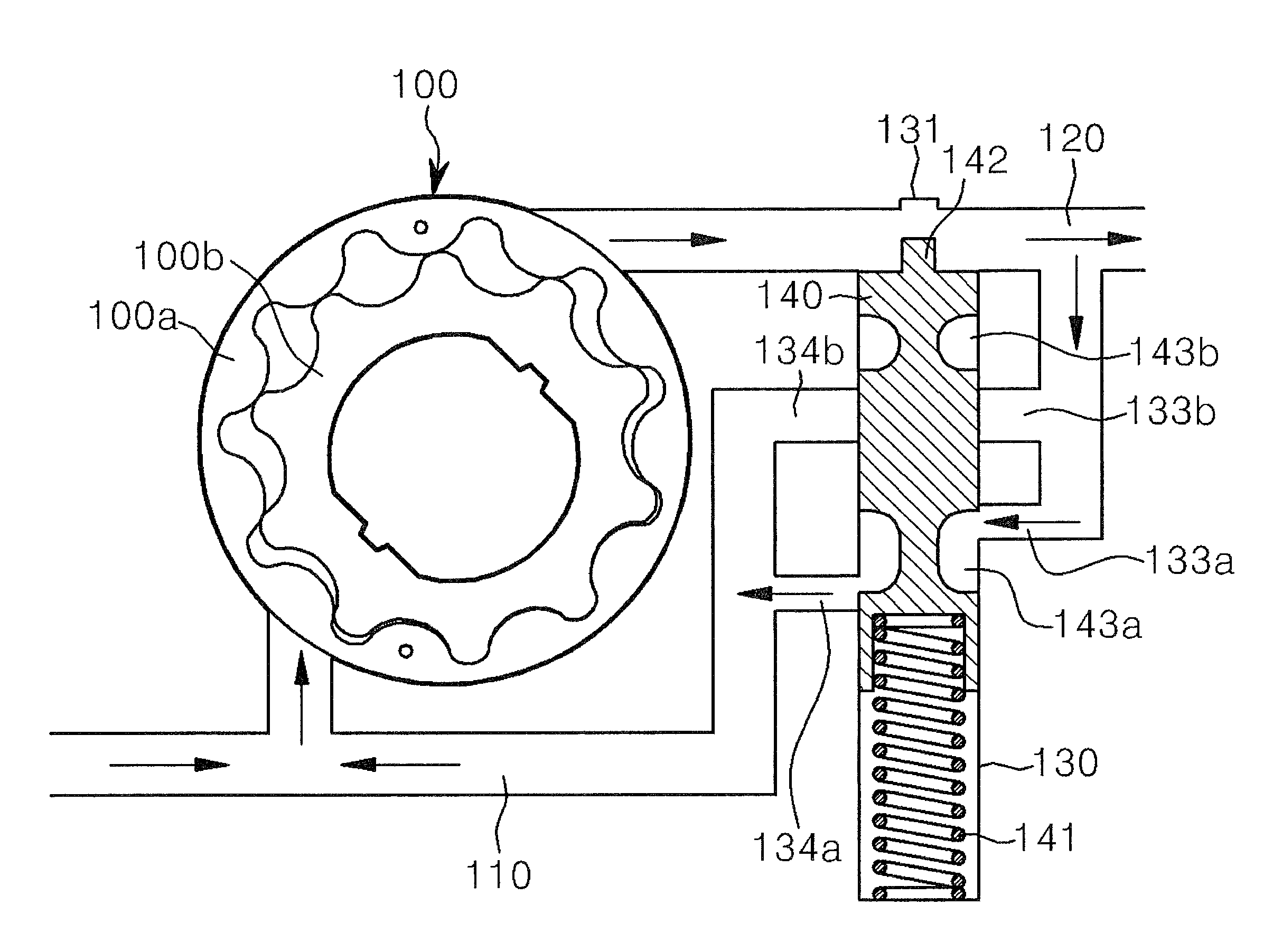
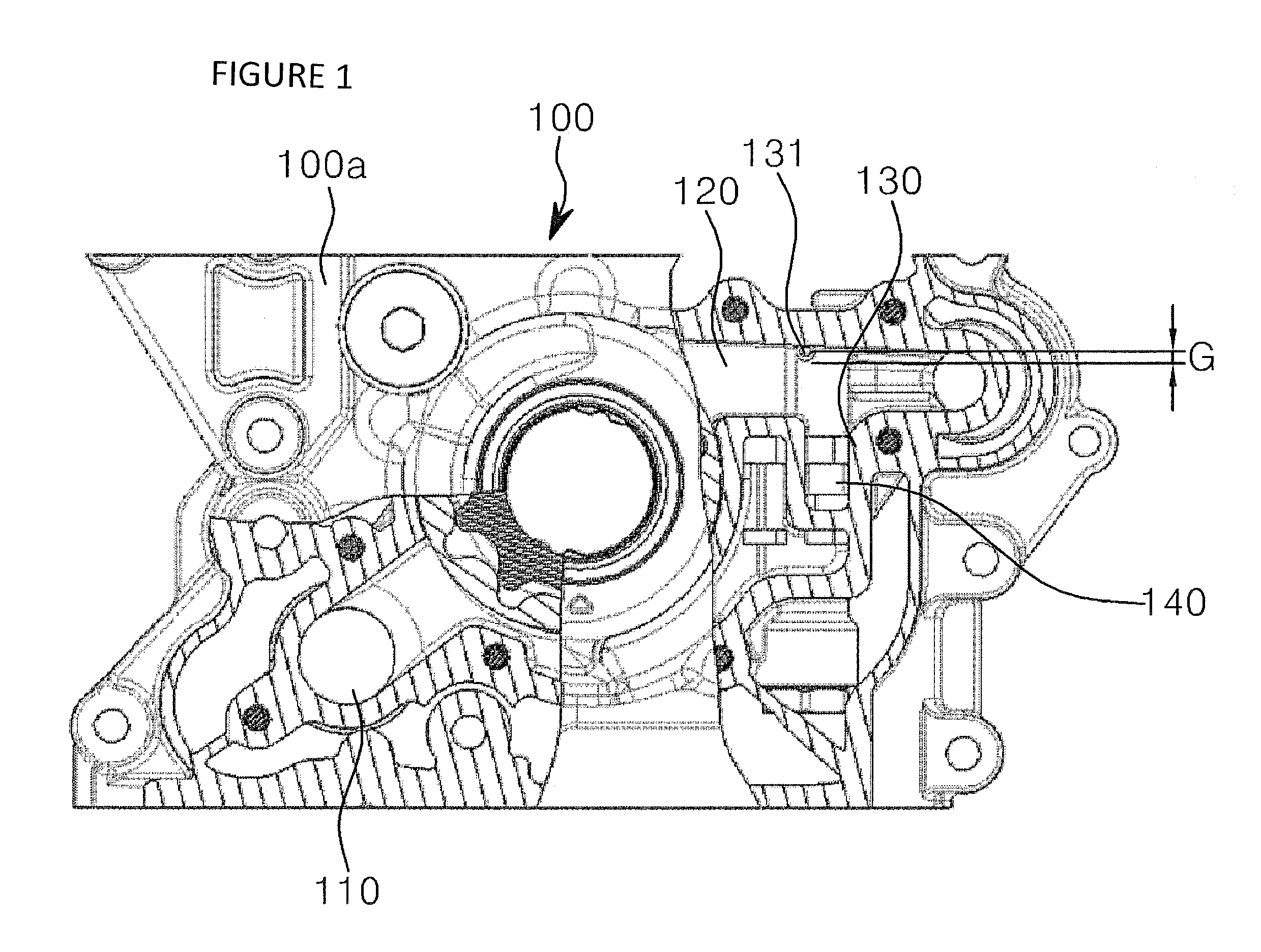
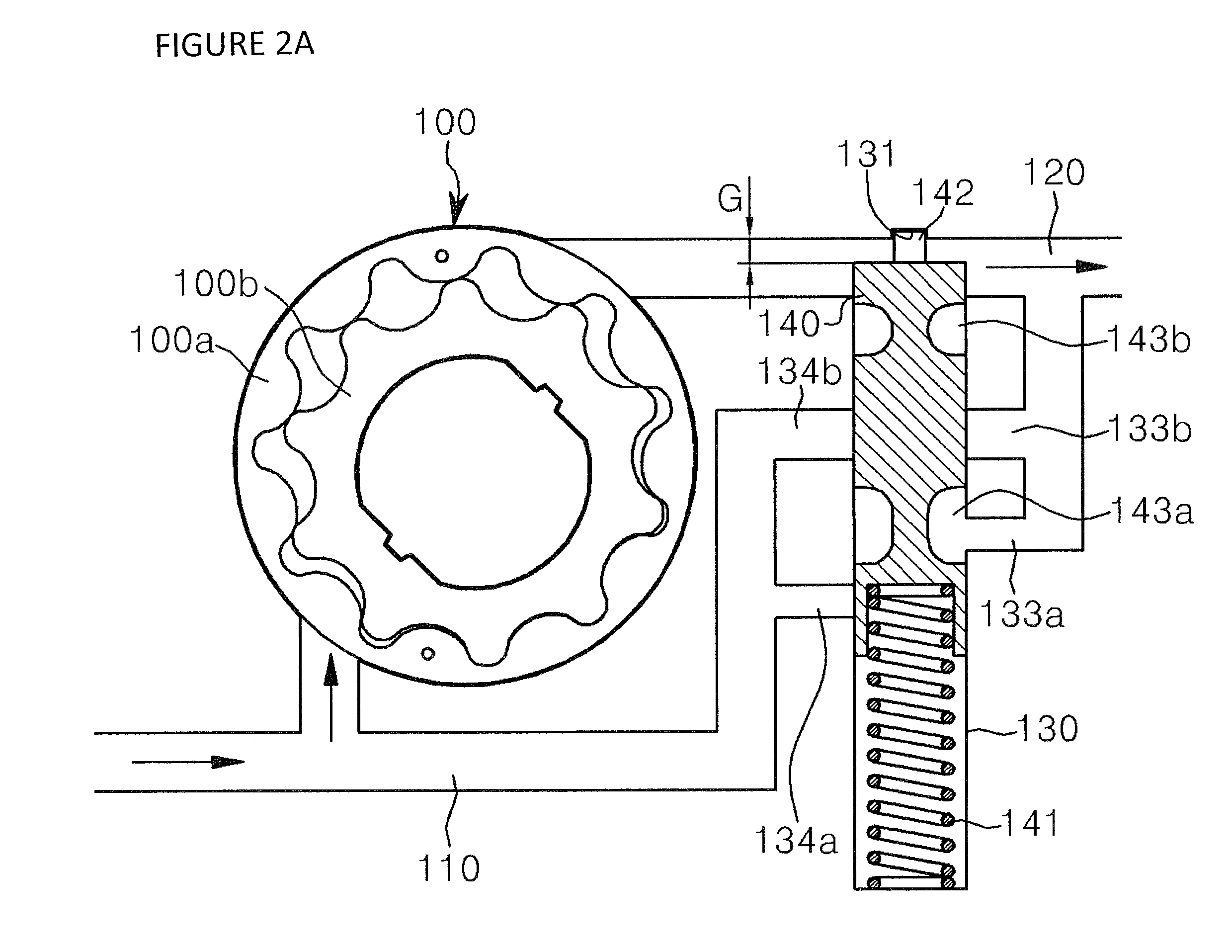
[0034]FIG. 1 is a cross-sectional view showing a structure of a variable oil pump in accordance with a first exemplary embodiment of the present invention, FIG. 2A is a schematic view showing an operating state of the variable oil pump in accordance with a first exemplary embodiment of the present invention in a low speed range,FIG. 2B is a schematic view showing an operating state of the variable oil pump in accordance with a first exemplary embodiment of the present invention in a medium speed range, FIG. 2C is a schematic view showing an operating state of the variable oil pump in accordance with a first exemplary embodiment of the present invention in a medium / high speed range, FIG. 2D is a schematic view showing an operating state of the variable oil pump in accordance with a first exemplary embodiment of the present invention in a high speed range, and FIG. 3 is a graph showing variation in pressure of the variable oil pump in accordance with a first ex...

second embodiment

[0053][Second Embodiment]

[0054]FIG. 4 is a cross-sectional view showing a configuration of a variable oil pump in accordance with a second exemplary embodiment of the present invention, FIG. 5 is a perspective view showing a configuration of a plunger in accordance with a second exemplary embodiment of the present invention, FIG. 6 is a plan view showing the configuration of the plunger in accordance with a second exemplary embodiment of the present invention, FIG. 7 is an enlarged view of a portion of FIG. 6, and FIG. 8 is a graph showing variation in pressure of the variable oil pump in accordance with a second exemplary embodiment of the present invention according to an engine speed. Here, like elements of the first embodiment are designated by like reference numerals, and thus, detailed description will not be repeated.

[0055]A variable oil pump in accordance with a second exemplary embodiment of the present invention is distinguished from the first embodiment by a configuration...


PUM


Abstract

A variable oil pump capable of rapidly ejecting a required amount of working fluid using an oil pressure of the working fluid generated according to an engine RPM, and improving a lubrication effect to improve engine efficiency. Also described is a variable oil pump, in which a gap is provided between a plunger and a cylinder to easily operate the plunger using an oil pressure output from an oil pump, enabling more rapid supply of a required amount of oil using an oil pressure varied according to variation in an engine RPM. A variable oil pump is described in which the plunger is perpendicularly operated with respect to a flow direction of the working fluid, such that the plunger can be operated in a direction in which a pressure of the working fluid is applied to operate the oil pump.

Description

BACKGROUND[0001]1. Field of the Invention[0002]The present invention relates to a variable oil pump, and more particularly, to a variable oil pump capable of, when oil is supplied to a power generating apparatus such as an engine, preventing the oil from being excessively supplied in a medium speed range and a high speed range, sufficiently supplying the oil in a low speed range and a medium / high speed range, and thereby preventing unnecessary supply of the oil with a simple structure.[0003]2. Discussion of Related Art[0004]In general, an engine requires a lubrication apparatus that can lubricate operating components such as a piston and a crankshaft. In particular, the lubrication apparatus requires an oil supply apparatus such as an oil pump that can supply a working fluid such as oil to places where a lubrication operation is needed.[0005]In particular, a rotor-type oil supply apparatus is connected to a crankshaft to be used to adjust an ejected amount of a working fluid in prop...

Claims


Application Information

Patent Timeline
Patent Type & Authority Patents(United States)
IPC IPC(8): F04C28/26
CPCY10T137/86171F04C2210/206F04C2/10Y10T137/2663F04C14/26
Inventor KWON, HYUK INKIM, JIN YONG
Owner MEIWA IND CO LTD
Why Eureka
Try Eureka