Supercharge Your Innovation With Domain-Expert AI Agents!

Pressure relief valve

a pressure relief valve and valve body technology, applied in the direction of functional valve types, machines/engines, positive displacement liquid engines, etc., can solve the problems of inability to accurately display the pressure measured, inconvenience for users performing such operations, etc., and achieve the effect of facilitating air filling or pressure reli

Inactive Publication Date: 2014-09-16
WENG CHEN YUAN +1
View PDF7 Cites 3 Cited by
  • Summary
  • Abstract
  • Description
  • Claims
  • Application Information

AI Technical Summary

Benefits of technology

The present invention provides an improved pressure relief valve that helps alleviate air pressure in air-filing articles such as tires. It includes a pressure adjustor for setting a pressure value and an anti-leakage rubber to release air when the pressure reaches the set value. The valve has a conduit with an abutting portion and an anti-reverse unit to prevent air from escaping during pressure relief. The valve is fastened to an air pumping device and the air-filling article, allowing for easy air filling without the need for a separate connector. The valve has a slanted section and an anti-reverse unit that can block the slanted section to facilitate air filling or pressure relief. Overall, this valve helps to maintain a stable filling state and prevents excess air pressure during air filling.

Problems solved by technology

Due to the different elastic properties of the tires to be filled with air vary from one another and since the pressure value of the filled tire cannot be immediately known to users, in order to maintain a proper tire pressure that is neither too great or less, the users often use hands or pressure gauges at the air intakes of the tires to measure the tire pressure, which can be inconvenient to the users performing such operations.
In addition, although most air pumping devices are equipped with pressure gauges, the values shown by the pressure gauges are often for reference only and cannot accurately display the pressure measured.

Method used


Image

  • Pressure relief valve
  • Pressure relief valve
  • Pressure relief valve

Examples


Embodiment Construction

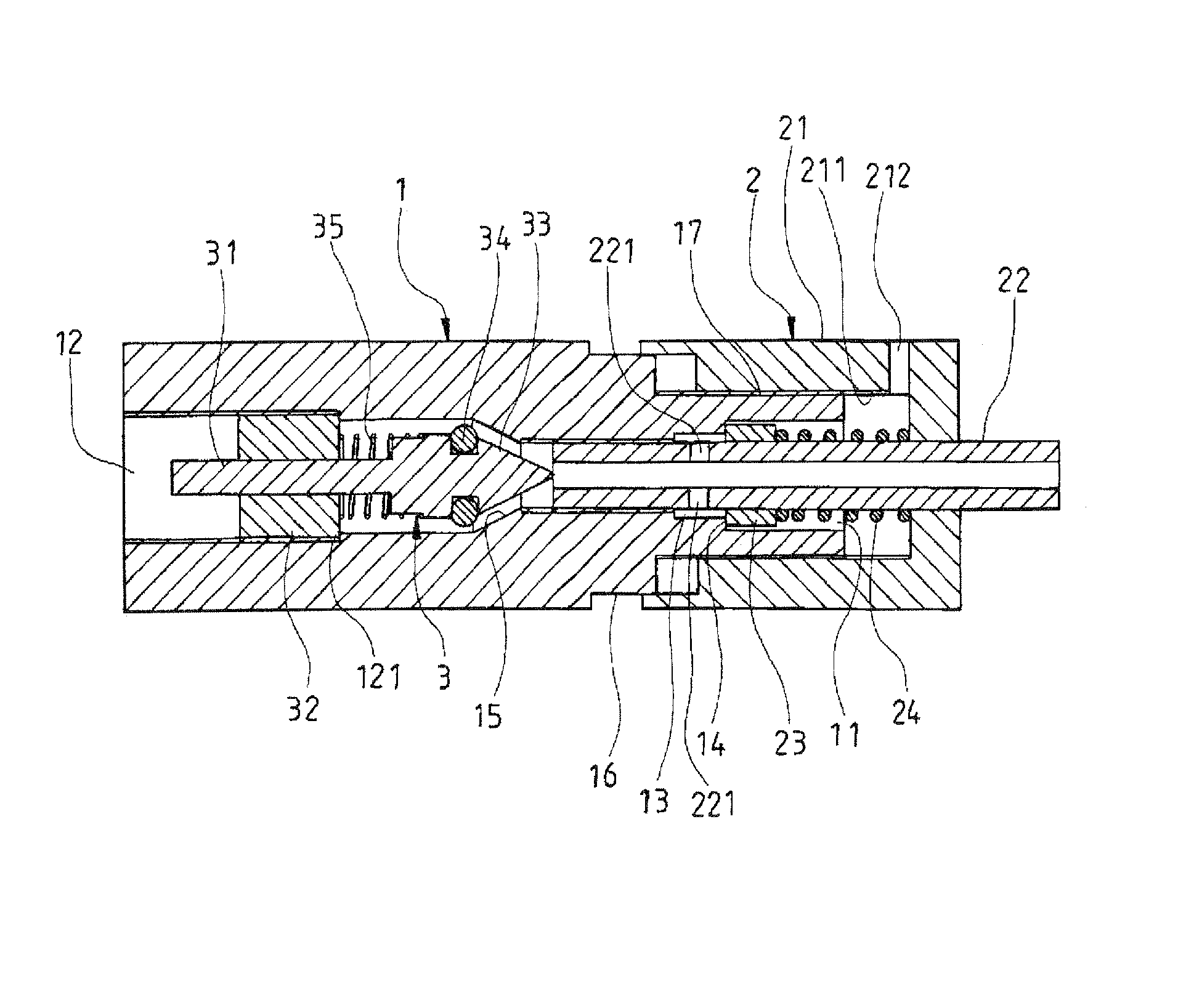
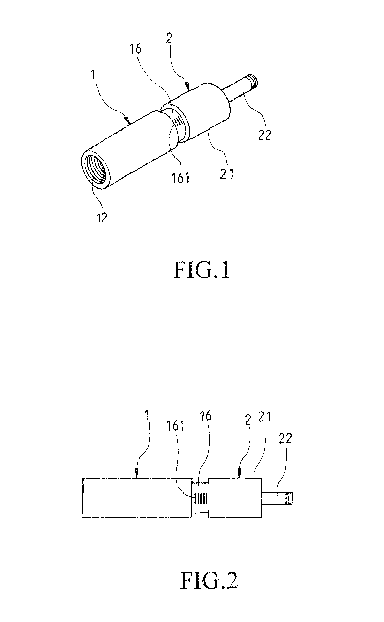
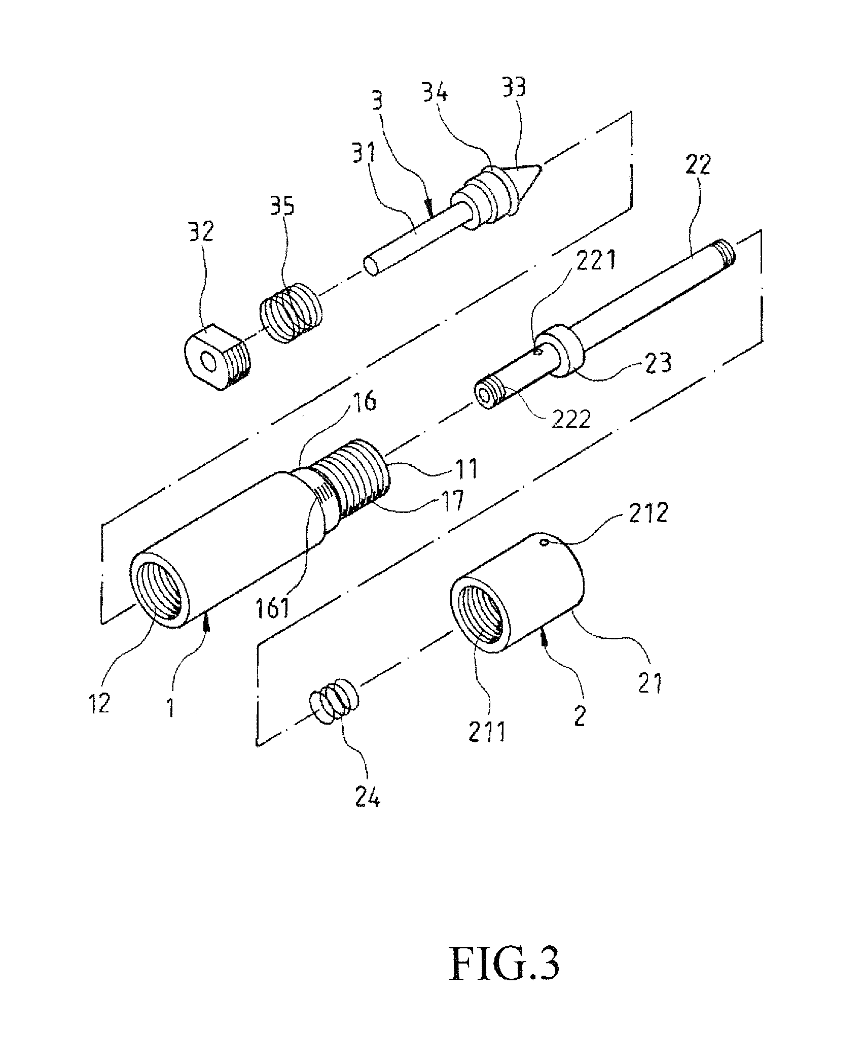
[0017]FIGS. 1, 2, 3 and 4 show the perspective view, side view, exploded view and cross sectional view of the improved pressure relief valve of the present invention respectively. As shown in the figures, the improved pressure relief valve of the present invention comprises a tubular main body 1, a pressure adjustor 2 and an anti-reverse unit 3. In addition, the main body 1 comprises a mount opening 11 and an air outlet 12 on two ends thereof respectively. A conduit 13 is provided between the mount opening 11 and the air outlet 12; wherein an abutting portion 14 in a staged shape is provided at a connecting end between the conduit 13 and the mount opening 11, and a slanted section 15 in a cone shape is provided at a connecting end between the conduit 13 and the air outlet 12. Furthermore, a staged portion 121 is provided between the slanted section 15 and the air outlet 12. An outer surface of the mount opening 11 of the main body 1 comprises an attachment portion 16 and a threaded ...


PUM


Abstract

The present invention provides an improved pressure relief valve comprising a tubular main body with a pressure relief peroration, a pressure adjustor with an anti-leakage rubber and an anti-reverse unit; wherein the main body comprises a mount opening, an air outlet and a conduit between the air intake and outlet. The conduit comprises an abutting portion; the pressure adjustor is mounted on the air intake and the anti-reverse unit is fastened onto said outlet. As the pressure adjustor is connected to an air pump and said outlet is connected to an air-filling article, the pressure value of said article is set via the pressure adjustor. As said article reaches said pressure value, the anti-leakage rubber of the pressure adjustor is pushed such that air is released from the relief perforation and the anti-reverse unit abuts the staged portion of the conduit to maintain the article at a stabilized filling state.

Description

TECHNICAL FIELD OF THE INVENTION[0001]The present invention is related to an improved pressure relief valve, in particular, to an improved pressure relief valve provided for connecting with an air pumping device and air filled article to preset a pressure value of the air-filling article such that as the air-filling article reaches the preset pressure value, the air can be released from the pressure relief valve thereof in order to keep the air-filling article filled with air at a stable pressure.DESCRIPTION OF THE PRIOR ART[0002]For conventional tires of vehicles including such as bicycles, the air intake of the air-filling articles of the tires is normally connected to an air pumping device via a pipe such that the air can be pumped into the tire. Due to the different elastic properties of the tires to be filled with air vary from one another and since the pressure value of the filled tire cannot be immediately known to users, in order to maintain a proper tire pressure that is ne...

Claims


Application Information

Patent Timeline
Patent Type & Authority Patents(United States)
IPC IPC(8): F16K15/20F16K17/04
CPCB60S5/043F04B33/005F16K17/048Y10T137/3646Y10T137/7922Y10T137/87861
Inventor WENG, CHEN-YUANHO, CHIN-SHENG
Owner WENG CHEN YUAN
Features
  • R&D
  • Intellectual Property
  • Life Sciences
  • Materials
  • Tech Scout
  • Unparalleled Data Quality
  • Higher Quality Content
  • 60% Fewer Hallucinations
Learn More