Circuit breaker, circuit breaker terminal lug cover, and method of protecting a terminal lug

a terminal lug and circuit breaker technology, applied in the direction of protective switch terminal/connection, circuit-breaking switch, connection to coupling devices, etc., can solve the problems of cable melting, high temperature exhaust gas, terminal lug damage,

Active Publication Date: 2014-10-07
EATON INTELLIGENT POWER LTD
View PDF14 Cites 15 Cited by
  • Summary
  • Abstract
  • Description
  • Claims
  • Application Information

AI Technical Summary

Benefits of technology

[0012]These needs and others are met by embodiments of the disclosed concept in which a circuit breaker terminal lug cover protects a circuit breaker terminal lug and a number of connecting cables from degradation or corrosion (e.g., without limitation, caused by heat and / or ionized exhaust gases).
[0013]In accordance with one aspect of the disclosed concept, a circuit breaker terminal lug cover is structured to mechanically secure to a circuit breaker terminal lug and protect the terminal lug from degradation or corrosion, the terminal lug includes a number of terminal lug screws capable of securing a number of cables to the circuit breaker. The terminal lug cover comprises: a plurality of sides structured to carry heat away from the terminal lug or deflect ionized gases away from the terminal lug, wherein at least one of the sides includes a number of securing members structured to mechanically secure the terminal lug cover to the circuit breaker terminal lug, and wherein one of the sides includes an access hole permitting access to the number of terminal lug screws.
[0016]As another aspect of the disclosed concept, a method protects a circuit breaker terminal lug from degradation or corrosion. The circuit breaker terminal lug includes a number of terminal lug screws capable of securing a number of cables to a circuit breaker, and the circuit breaker includes a terminal lug. The method comprises: mechanically securing a circuit breaker terminal lug cover to the circuit breaker terminal lug in order to protect the terminal lug from degradation or corrosion; providing the circuit breaker terminal lug cover with a plurality of sides structured to carry heat away from the terminal lug or deflect ionized gases away from the terminal lug; including with at least one of the sides a number of securing members mechanically securing the terminal lug cover to the circuit breaker terminal lug; and providing one of the sides with an access hole permitting access to the number of terminal lug screws.

Problems solved by technology

When the circuit breaker interrupts the overload or short circuit current, an arc is generated, which creates exhaust gases of high temperature.
These ionized exhaust gases can damage the terminal lug of the circuit breaker by causing corrosion.
Additionally, the heated exhaust gases can damage the circuit breaker terminal lug by causing connecting cables to melt onto the terminal lug.
Corrosion of the terminal lug coupled with melted cable material can damage terminal lug screw threads rendering the threads and terminal lug unusable.
When the cabling connected to a circuit breaker melts onto the terminal lug, such that removal thereof becomes difficult, it is standard practice to cut the damaged cabling.
Additionally, when circuit breaker terminal lugs have degraded to such a degree that corrosion and cable melt have made the terminal lug and threads therein unusable, it is standard practice to replace the terminal lug, or in some cases, the entire circuit breaker.
However, it is believed that the teachings found in this Patent suffer from the fact that it is not easily adaptable to interface between a commercial circuit breaker and its terminal lug.
It is believed that such terminal shields fail to properly address or protect external circuit breaker terminal lugs and connecting cables from such arcing events.

Method used


Image

  • Circuit breaker, circuit breaker terminal lug cover, and method of protecting a terminal lug
  • Circuit breaker, circuit breaker terminal lug cover, and method of protecting a terminal lug
  • Circuit breaker, circuit breaker terminal lug cover, and method of protecting a terminal lug

Examples


Embodiment Construction

[0024]As employed herein, the term “number” shall mean one or an integer greater than one (i.e., a plurality).

[0025]As employed herein, the statement that two or more parts are “connected” or “coupled” or “affixed” together shall mean that the parts are joined together either directly or joined through one or more intermediate parts. Further, as employed herein, the statement that two or more parts are “attached” shall mean that the parts are joined together directly.

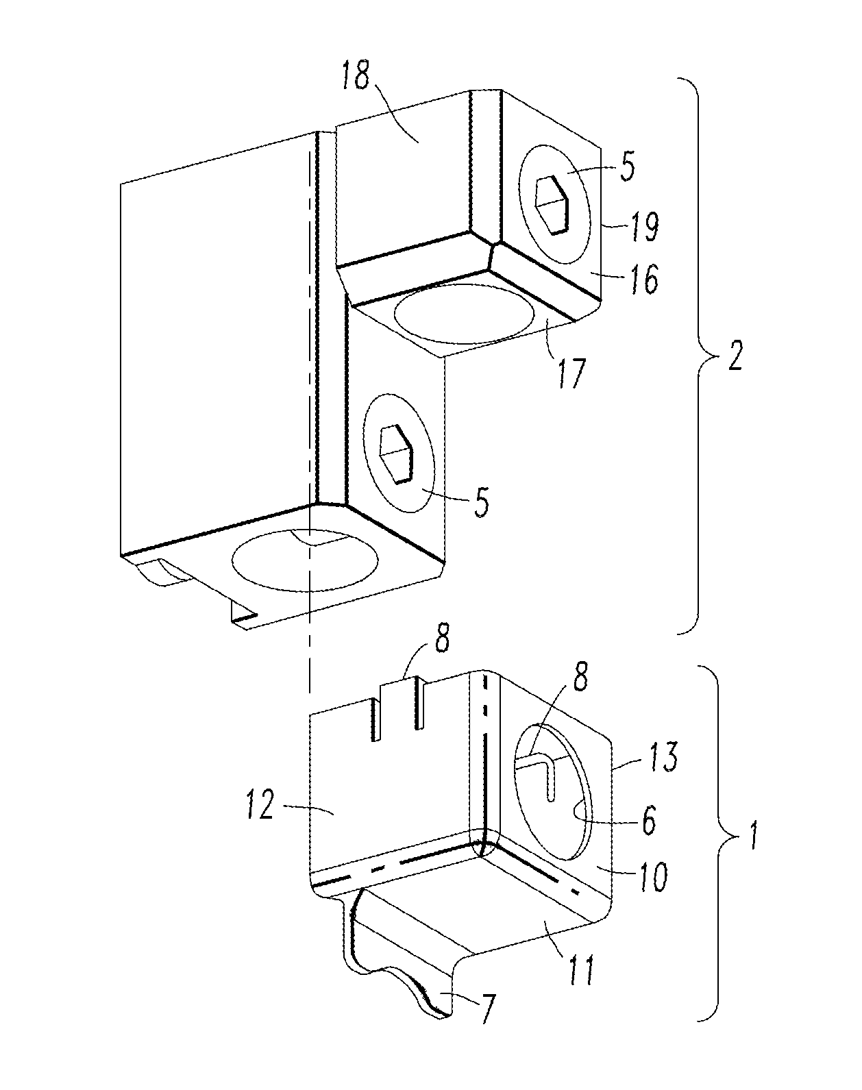
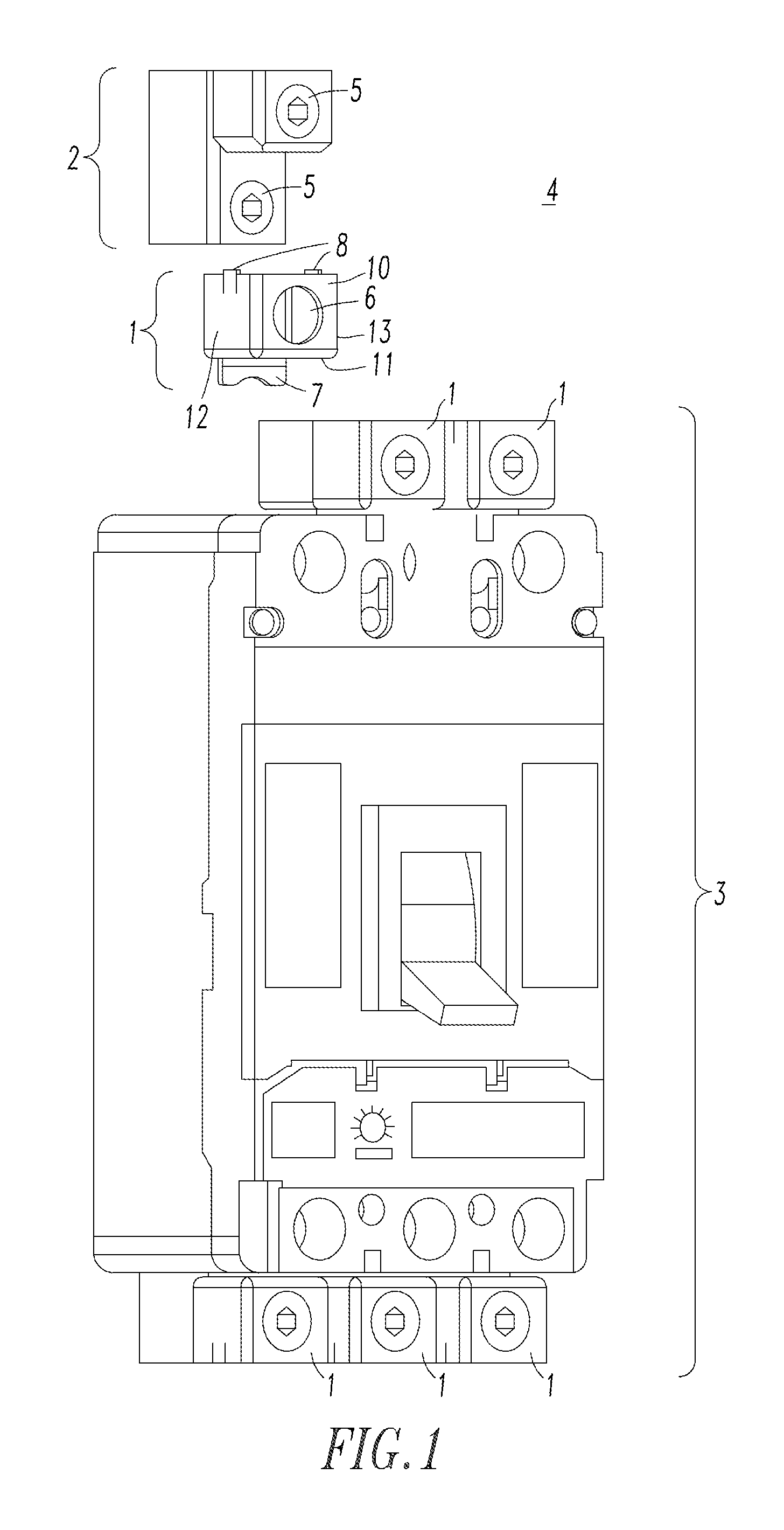
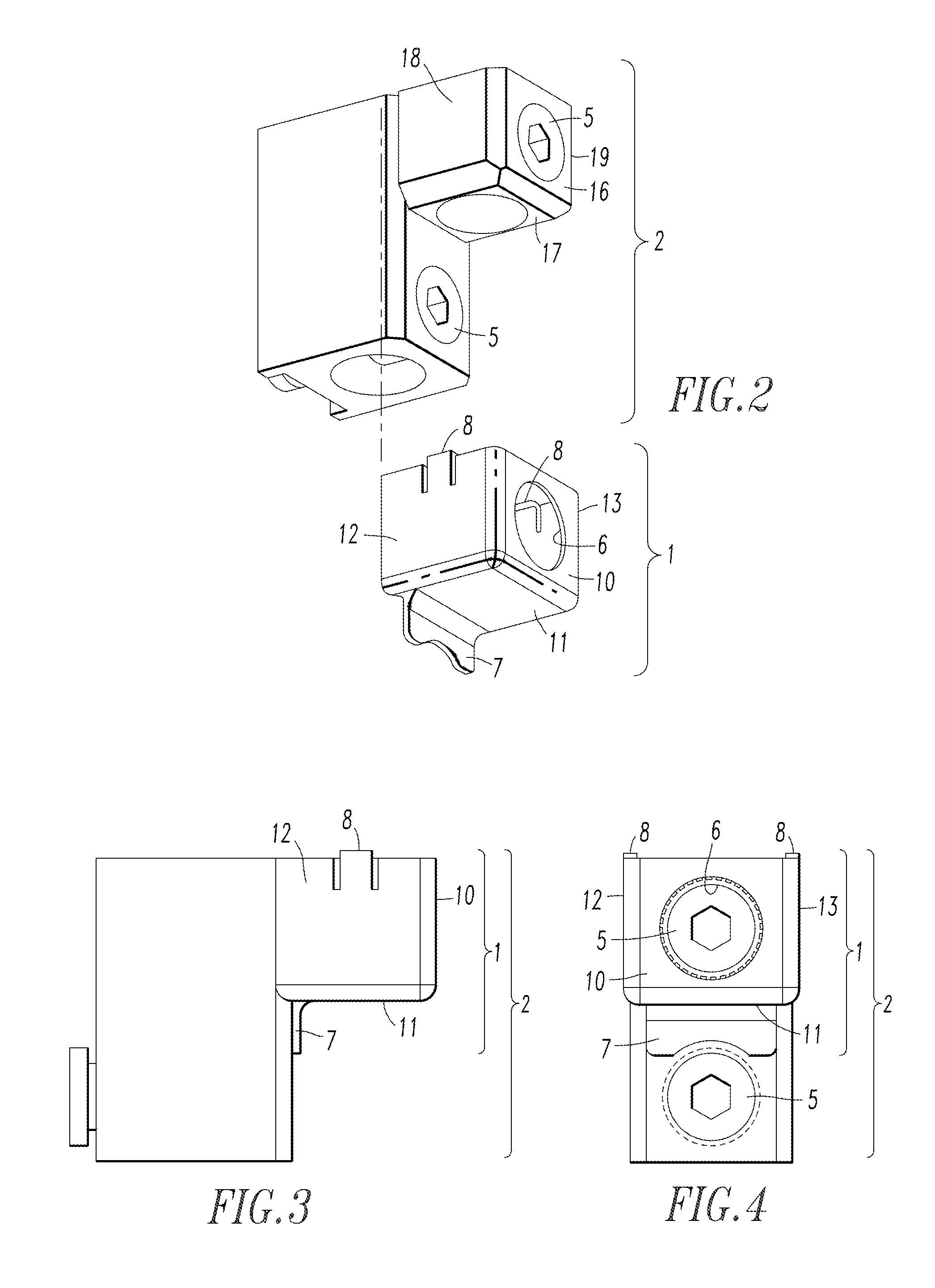
[0026]As employed herein, the term “circuit breaker” shall mean any electrical switch or circuit interrupter that interrupts the flow of electrical current in an electrical circuit upon the existence or occurrence of specified number of electrical / mechanical fault conditions, and that permits the flow of electric current in the electrical circuit under other conditions.

[0027]As employed herein, the term“circuit breaker terminal” shall mean a component of a circuit breaker that permits a number of cables of a circuit to ...


PUM

PropertyMeasurementUnit
corrosionaaaaaaaaaa
vertical lengthaaaaaaaaaa
temperatureaaaaaaaaaa

Abstract

A circuit breaker terminal lug cover is structured to mechanically secure to a circuit breaker terminal lug and protect the terminal lug from degradation or corrosion. The terminal lug includes a number of terminal lug screws capable of securing a number of cables to the circuit breaker. The terminal lug cover includes a plurality of sides structured to carry heat away from the terminal lug or deflect ionized gases away from the terminal lug. At least one of the sides includes a number of securing members structured to mechanically secure the terminal lug cover to the circuit breaker terminal lug. One of the sides includes an access hole permitting access to the number of terminal lug screws.

Description

CROSS REFERENCE TO RELATED APPLICATION[0001]This application claims the benefit of U.S. Patent Application Ser. No. 61 / 569,726, filed Dec. 12, 2011, which is incorporated by reference herein.BACKGROUND[0002]1. Field[0003]The disclosed concept pertains generally to heat and corrosion protection devices and, more particularly, to devices used to protect circuit breaker terminals, terminal screw threads, connecting cables, and the like, from heat and corrosion caused by high temperature gases. The disclosed concept further pertains to circuit breakers. The disclosed concept also pertains to methods of protecting circuit breaker terminals, terminal screw threads, connecting cables, and the like.[0004]2. Background Information[0005]Circuit breakers function to interrupt the flow of electric current when an overload or short circuit is detected within a power circuit. When the circuit breaker interrupts the overload or short circuit current, an arc is generated, which creates exhaust gase...

Claims


Application Information

Patent Timeline
Patent Type & Authority Patents(United States)
IPC IPC(8): H01H9/02H01H69/00H01H71/08H01H77/00H01R13/533
CPCH01H77/00H01H69/00H01H71/08H01R13/533H01H9/0264Y10T29/49105
Inventor SISLEY, JAMES P.MERCK, PAUL A.MUELLER, ROBERT W.
Owner EATON INTELLIGENT POWER LTD
Why Eureka
Try Eureka