Detonation of explosives

a technology of explosives and detonators, which is applied in the direction of incandescent ignition, combustion process, combustion ignition, etc., can solve the problems of detonation of the main explosive charge, premature initiation of the detonator and thus of the explosive, and high manufacturing cost of the electronic detonator, so as to increase the conductance of the transistor

Active Publication Date: 2014-10-14
DETNET SOUTH AFRICA (PTY) LTD
View PDF19 Cites 13 Cited by
  • Summary
  • Abstract
  • Description
  • Claims
  • Application Information

AI Technical Summary

Benefits of technology

[0050]The switching device may, in particular be a transistor having a variable conductance which, in the non-detonation initiating condition, provides resistance against conduction of current from the voltage source to the resistive bridge such that the detonation initiating voltage cannot, in use, be generated between the resistive electrodes, with switching of the initiating device into the standby condition including increasing the conductance of the transistor. It will therefore be appreciated that, on being switched into the standby condition, generation of the detonation initiating voltage between the electrodes becomes possible, with the initiating device therefore be susceptible to be being switched to the detonation initiating condition.

Problems solved by technology

However, electronic detonators are expensive to manufacture and difficult to use usually also, requiring a separate or external power source and complex electronic transmission wire connections to allow transmission of electricity to the detonator and permit remote triggering thereof.
In the applicant's experience, such detonator connections are prone to failure and may even result in premature initiation of the detonator and thus of the explosive, possible due to false stimuli, e.g. radio-frequency (RF) interference on the mining / demolition site.
Upon reaching the detonator, the pressure / temperature wave triggers or ignites the initiating / sealing charge in the detonator, which results in the sequence of ignitions mentioned above and thus eventually causing detonation of the main explosive charge.
Although shock tube is economically attractive and easy to use, existing pyrotechnic-based detonator systems do not at all permit the same extent of control of detonation timing and delay which is achieved by using electronic detonators, as the timing and delay features are provided by the detonator explosive charge loading, instead of by electric components.

Method used


Image

  • Detonation of explosives
  • Detonation of explosives

Examples


Embodiment Construction

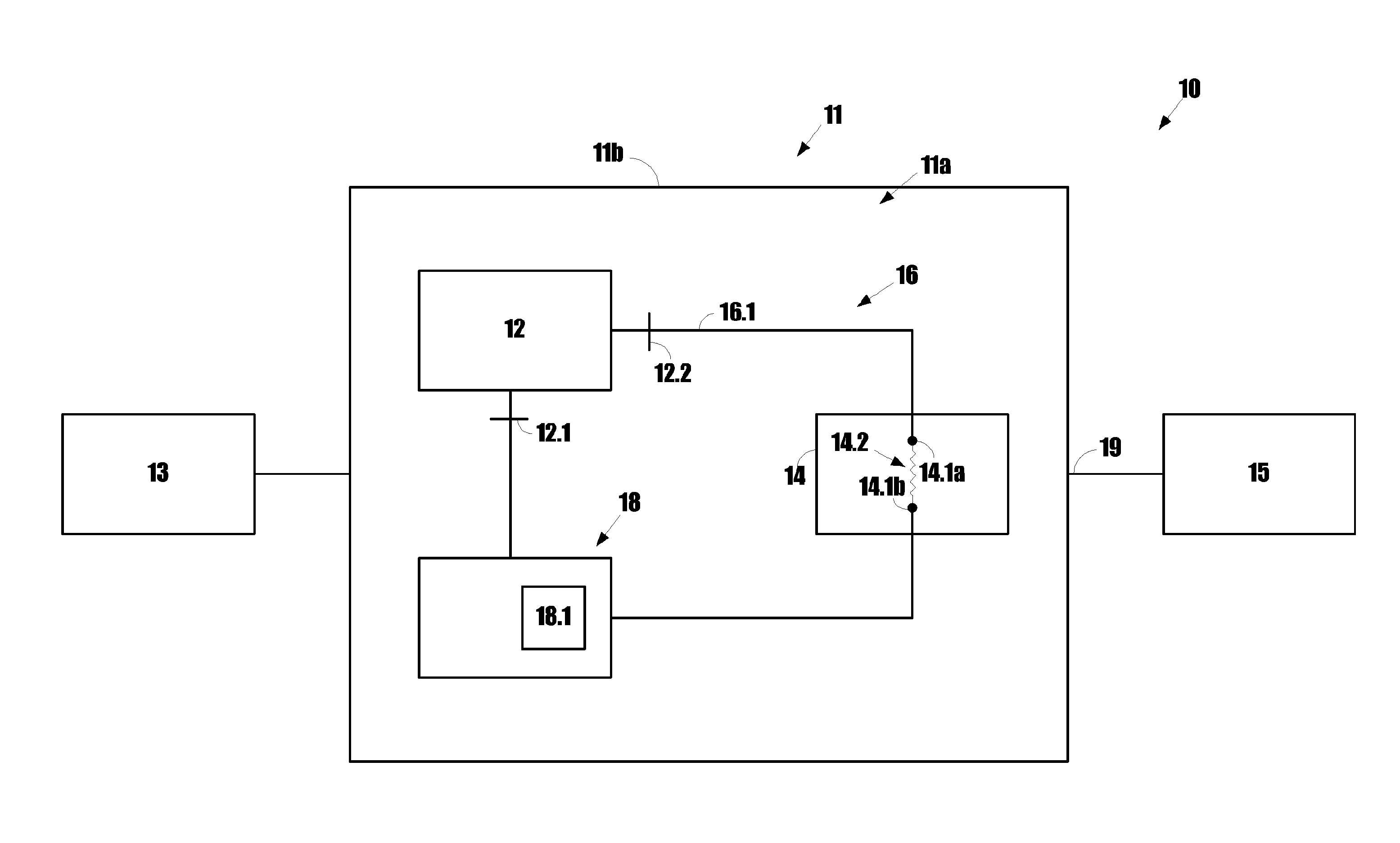
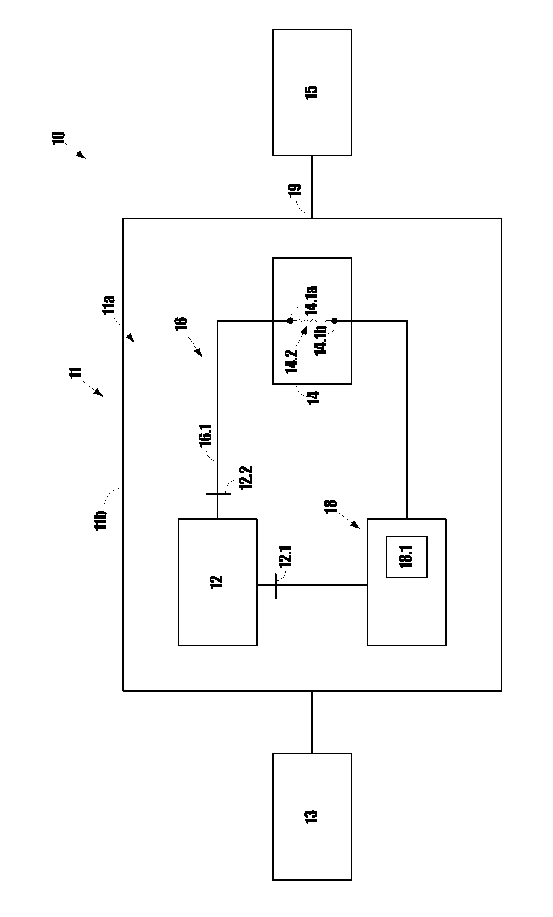
[0056]The invention will now be described by way of illustrative example only with reference to the accompanying diagrammatic drawing which shows, conceptually, an explosive detonator system in accordance with the invention.

[0057]Referring to FIG. 1, reference numeral 10 generally indicates an explosives detonation system in accordance with the invention. The system 10 includes a detonator 11 having an initiating device 11a, a shock tube 13, and an explosive charge 15, with which the detonator 11, and thus the initiating device thereof, is arranged in a detonating relationship. The initiating device 11a is provided inside a housing 11b of the detonator 11.

[0058]The shock tube 13 is arranged in an initiating relationship with the detonator 11, such arrangement being represented conceptually by connecting line 17. In practice, the shock tube 13 will typically be physically connected to the detonator 11, e.g. by means of a clamp or, more preferably, by being inserted into an open end o...


PUM

PropertyMeasurementUnit
response timeaaaaaaaaaa
external quantum efficiencyaaaaaaaaaa
responsivityaaaaaaaaaa

Abstract

An explosives detonator system for detonating an explosive charge with which it is, in use, arranged in a detonating relationship is provided. On acceptance of a detonation initiating signal having a detonation initiating property, the system initiates and thus detonates the explosive charge. The system includes an initiating device which accepts the detonation initiating signal and initiates and thus detonates the explosive charge. The initiating device is initially in a non-detonation initiating condition, in which it is not capable of accepting the detonation initiating signal. The system also includes a switching device that detects a chemical compositional component as a switching property of a switching signal that is transmitted to the detonator system, with the switching device being capable of switching the initiating device, on detection of the chemical compositional component, to a standby condition in which the initiating device accepts the detonation initiating signal when it is transmitted thereto.

Description

[0001]This application claims priority to International Application No. PCT / IB2011 / 055576 filed Dec. 9, 2011; South African Application No. 2010 / 08925 filed Dec. 10, 2010; South African Application No. 2010 / 08927 filed Dec. 10, 2010; and South African Application No. 2011 / 01370 filed Feb. 21, 2011, the entire contents of each are incorporated herein by reference.FIELD OF THE INVENTION[0002]This invention relates to detonation of explosives. More particularly, the invention relates to detonator systems for detonating explosives with which they are arranged in a detonating relationship. The invention accordingly provides a detonator system for detonating an explosive charge with which it is, in use, arranged in a detonating relationship. The invention also provides a method of operating a detonator system. The invention further provides a shock tube.BACKGROUND TO THE INVENTION[0003]Detonation of explosive charges is generally effected by means of detonators which are provided in a det...

Claims


Application Information

Patent Timeline
Patent Type & Authority Patents(United States)
IPC IPC(8): F42C15/38F42C19/12F42B3/113F42B3/18F42B3/12F42D1/05C06C5/06
CPCF42D1/05C06C5/06F42B3/18F42C19/12F42C15/38F42B3/12
Inventor MULLER, ELMARHALLIDAY, PIETER STEPHANUS JACOBUSMORGAN, CLIFFORD GORDONDASTOOR, PAULBELCHER, WARWICKZHOU, XIAOJINGBRYANT, GLENN
Owner DETNET SOUTH AFRICA (PTY) LTD
Why Eureka
Try Eureka