Vacuum pump system for light gases

a vacuum pump and light gas technology, applied in the direction of pump control, non-positive displacement fluid engine, positive displacement liquid engine, etc., can solve the problems of less suitable systems, conventional fore-vacuum pump systems are not in position to handle a large quantity of gases, and conventional fore-vacuum pump systems are hardly suitable for handling light gases, etc., to achieve significant additional costs and facilitate conversion

Inactive Publication Date: 2006-04-25
PFEIFFER VACUUM GMBH
View PDF8 Cites 16 Cited by
  • Summary
  • Abstract
  • Description
  • Claims
  • Application Information

AI Technical Summary

Benefits of technology

[0016]A particular advantage of a vacuum pump system according to the present invention consists in that the inventive system is compatible with conventional systems, i.e., they can be easily converted into a vacuum pump system for delivery of a large amount of a light gas, without significant additional expe

Problems solved by technology

For pumping light gases (e.g., H2, He), these systems are less suitable, in particular, when it is necessary to deliver a large quantity of gases.
Conventional fore-vacuum pump systems are not in position to handle a large quantity of gases that accumulates at the gas outlet of a high vacuum pump.
Up to the present, the conventional fore-vacuum pumps proved to be hardly suitable for handling light gases.
This requires in

Method used


Image

  • Vacuum pump system for light gases
  • Vacuum pump system for light gases
  • Vacuum pump system for light gases

Examples


Embodiment Construction

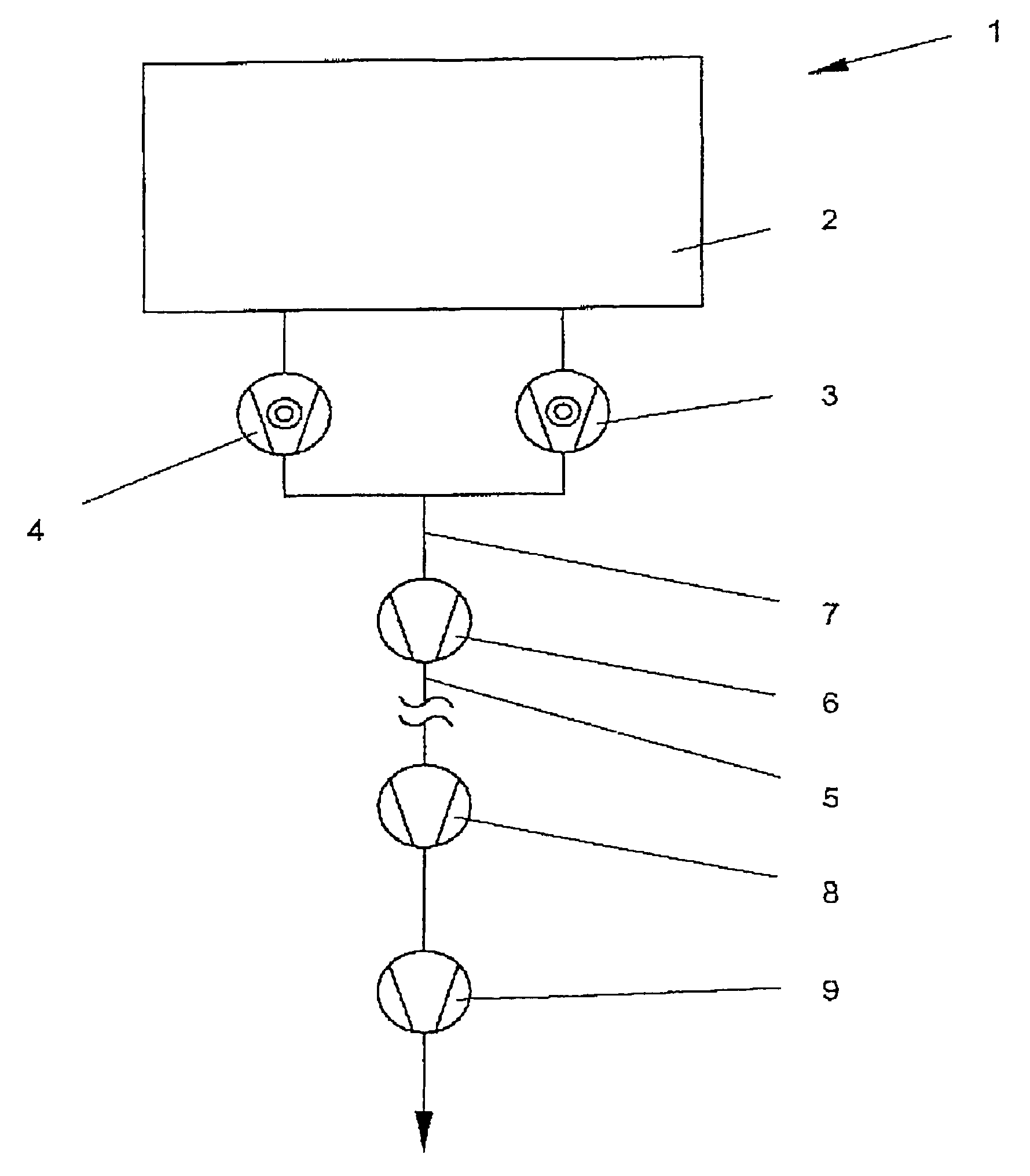
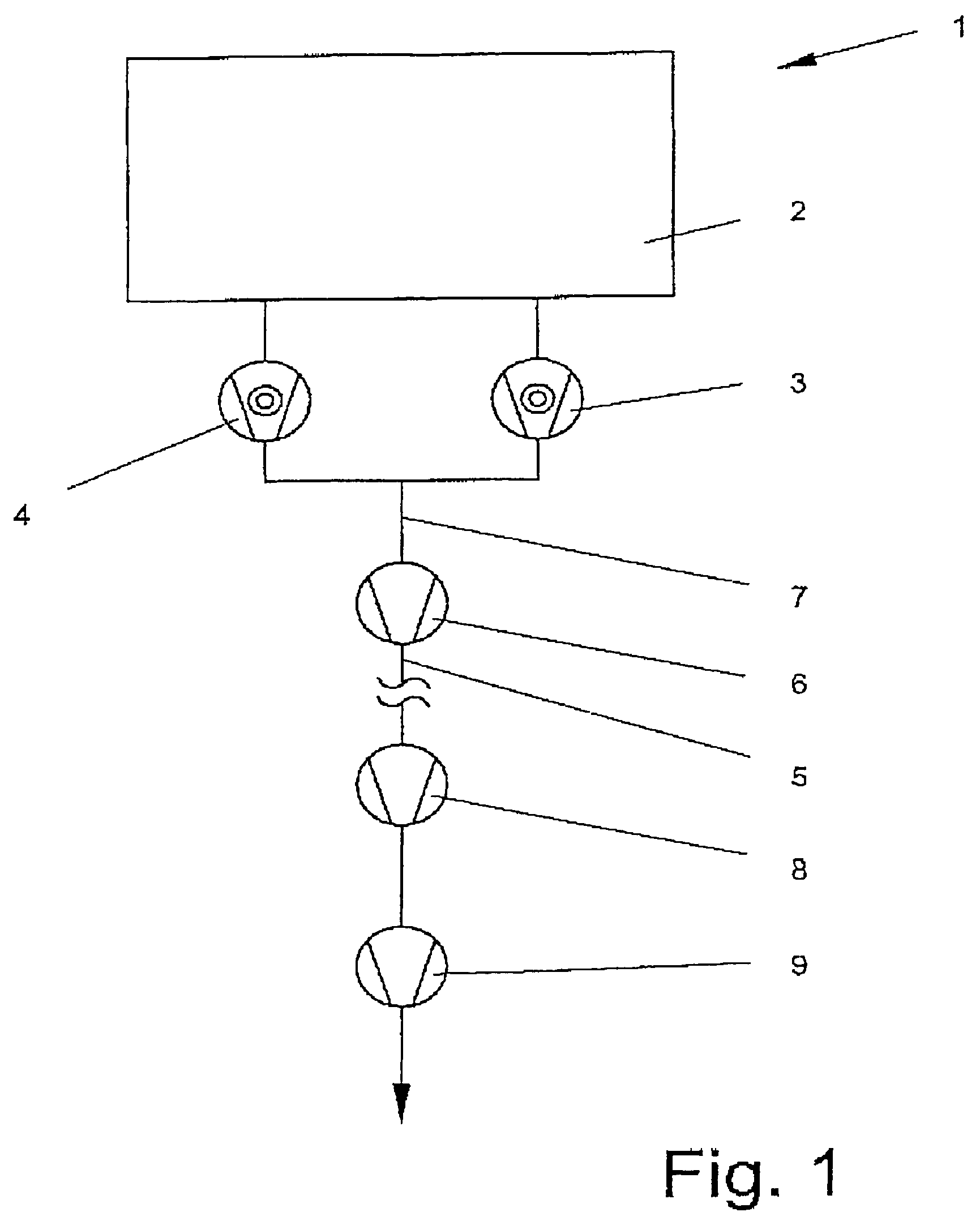
[0021]FIG. 1 shows a vacuum pump system (1). Two high-vacuum pumps, preferably turbomolecular pumps, are associated with the receiver (2). A fore-vacuum system consists of two fore-vacuum pumps (8, 9) for compressing the pumped gas to atmospheric pressure. According to the invention, an intermediate pump (6) is located between the high-vacuum pump (3, 4) and fore-vacuum pumps (8, 9) and is directly connected with a common outlet (7) of the high-vacuum pumps (3, 4). The intermediate pump (6) serves for delivering the gas pumped by the high-vacuum pumps (3, 4) to the fore-vacuum pumps (8, 9) without loss.

[0022]The fore-vacuum system is provided at the outlet side (5) of the intermediate pump 6.

[0023]An extended stretch path can lie between the intermediate pump (6) and the fore-vacuum pumps (8, 9).

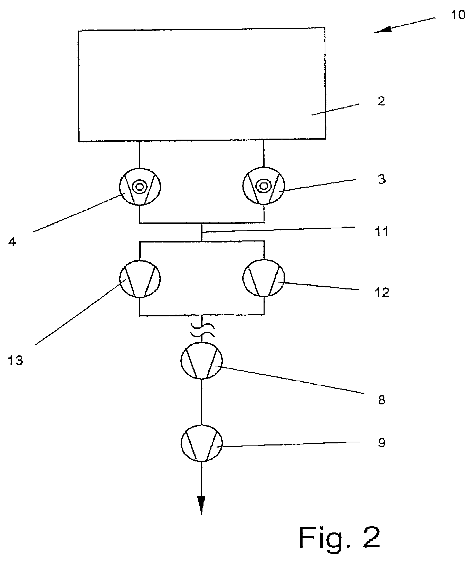
[0024]FIG. 2 shows a vacuum pump system (10). Again two high-vacuum pumps (3, 4) are associated with the receiver (2). Two intermediate pumps (12, 13) are provided downstream of a common out...


PUM


Abstract

A vacuum pump system includes at least one high-vacuum pump, a fore-vacuum pump, and at least one intermediate pump, arranged between the at least one high-vacuum pump and the fore-vacuum pump and having its inlet connected directly and exclusively with the outlet of the high-vacuum pump.

Description

BACKGROUND OF THE INVENTION[0001]1. Field of the Invention[0002]The present invention relates to a vacuum pump system for delivering light gases and including at least one high-vacuum pump.[0003]2. Description of the Prior Art[0004]A pump system for evacuating a receiver includes, e.g. a turbomolecular pump provided on the high-vacuum side and one or more fore-vacuum pumps for further delivering and for compressing to an atmospheric pressure gas that was condensed by the turbomolecular pump. These fore-vacuum pumps can be formed, e.g., as a combination of a rotary piston pump and a vane-type rotary pump, or as a dry compression pump discharged against atmospheric pressure. (DE-OS 38 28 608). Such pump systems are suitable for delivering and for compressing of gases with medium or high molecular weight (e.g., N2, O2, Ar). For pumping light gases (e.g., H2, He), these systems are less suitable, in particular, when it is necessary to deliver a large quantity of gases. In this case, oft...

Claims


Application Information

Patent Timeline
IPC IPC(8): F04B23/08F04D19/04F04D25/00F04D27/00
CPCF04D19/04F04D27/00F04D25/00
Inventor CONRAD, ARMINFAHRENBACH, PETERMADLER, MATTHIAS
Owner PFEIFFER VACUUM GMBH
Why Eureka
Try Eureka