Air vehicle having rotor/scissors wing

a technology of air vehicles and rotors, which is applied in the direction of vertical landing/take-off aircraft, efficient propulsion technologies, transportation and packaging, etc., can solve the problems of aircraft inefficient at airplane mode, low flying efficiency of invention, and compromising the key parameters of aerodynamic surfaces

Inactive Publication Date: 2003-12-30
CHEN ZHUO
View PDF21 Cites 112 Cited by
  • Summary
  • Abstract
  • Description
  • Claims
  • Application Information

AI Technical Summary

Problems solved by technology

A disadvantage of this invention is that different requirements to the canards and horizontal tail at different flying conditions force these aerodynamic surfaces to compromise their key parameters.
As the canards and horizontal tail should be large enough to generate almost all the lift for the aircraft but they are mainly used as control surfaces at airplane mode, they make the aircraft inefficient at airplane mode.
This invention has a disadvantage of low flying efficiency.
The relatively small and low aspect ratio stub blades are not efficient in generating lift at helicopter mode.
One disadvantage of this invention is its complexity.
Having so many control mechanisms, the hub is not only complex but also difficult to have small size thus generates considerable drag during high-speed flights.
Another disadvantage is poor controllability and stability.
During the conversion between helicopter mode and airplane mode, both of the rotor / wings have to keep generating lift to support the aircraft while they are being stopped or started to rotate, making the aircraft difficult to have good controllability and stability during the conversion.
These fixed sweep angles make a X-wing aircraft difficult to achieve efficient flying at a wide range of speed at airplane mode.

Method used


Image

  • Air vehicle having rotor/scissors wing
  • Air vehicle having rotor/scissors wing
  • Air vehicle having rotor/scissors wing

Examples


Embodiment Construction

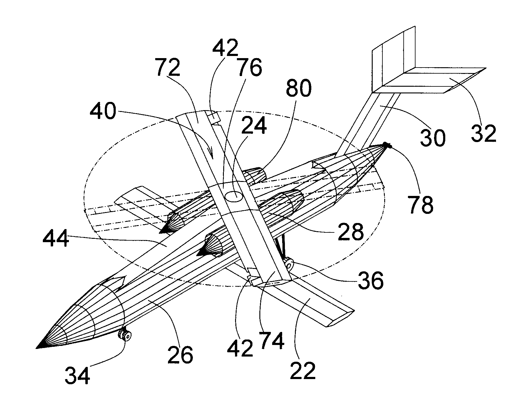
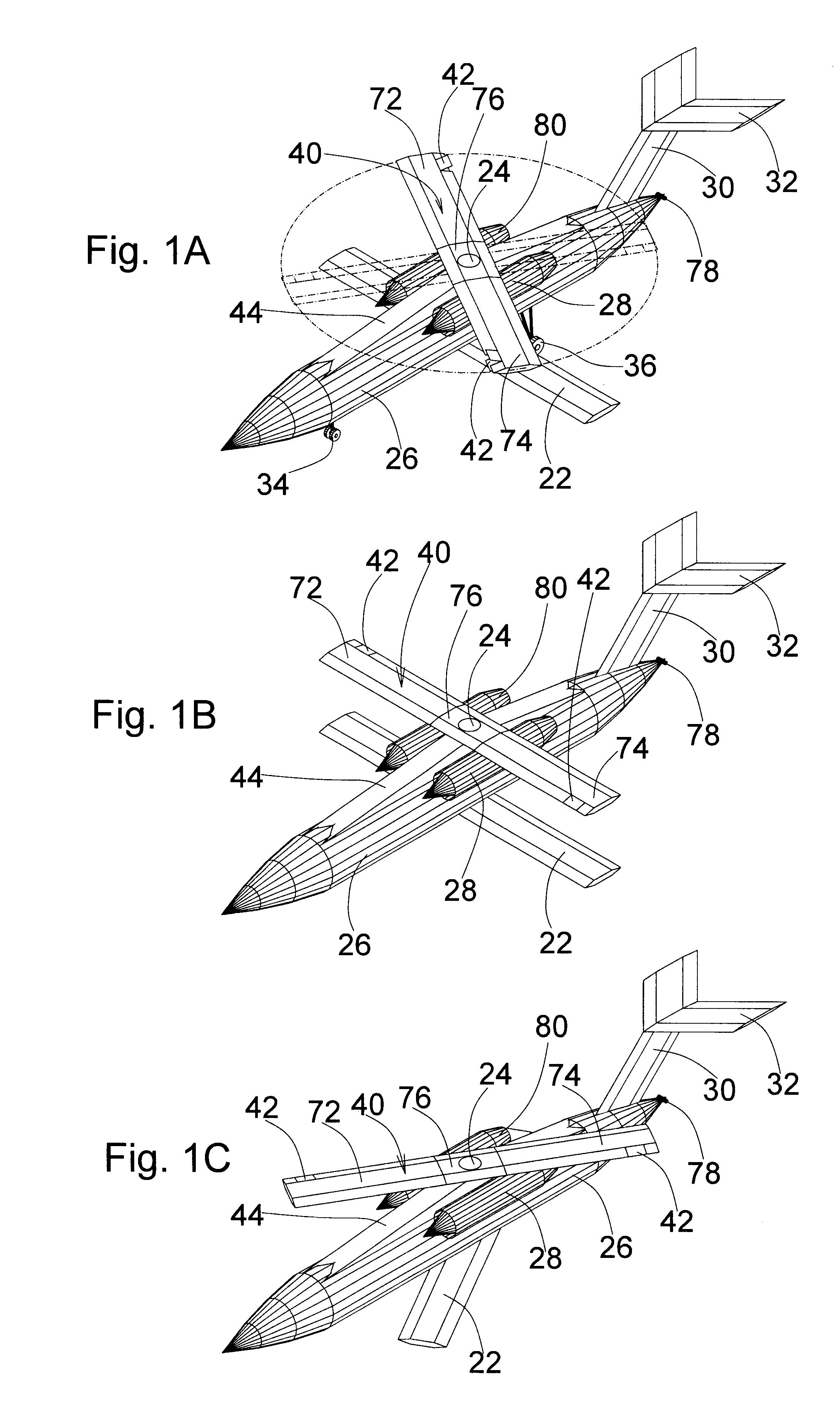
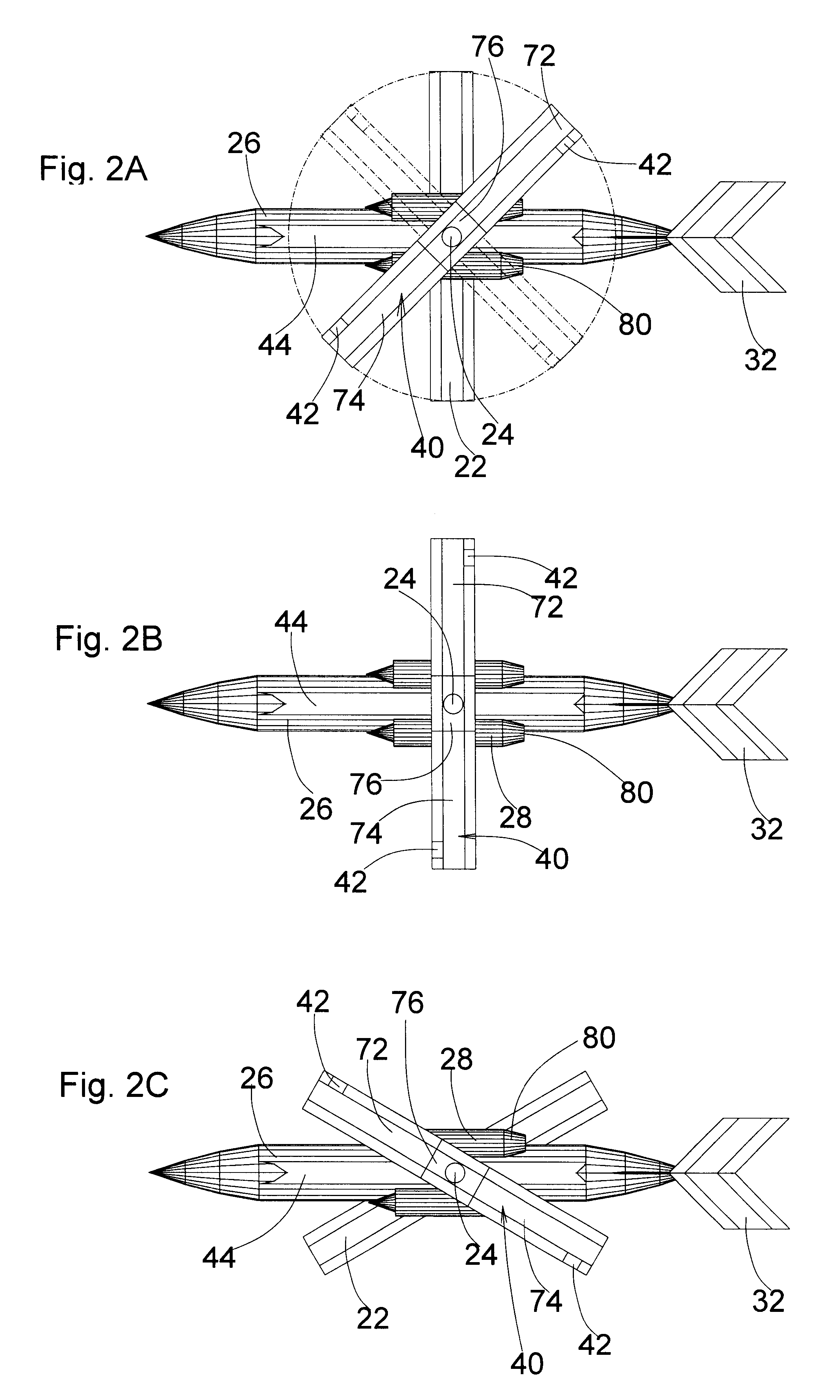
As shown in FIG. 1A, an aircraft with rotor / scissors wing is at helicopter mode in the condition of V / STOL, hovering, or low speed flying. Rotor / scissors wing 40 is installed above fuselage 26 via shaft 24. Fairing 44 is constructed between rotor / scissors wing 40 and fuselage 26 to reduce drag and contain systems like engine power transmission system and control system. Rotor / scissors wing 40 consists of a hub 76 and two blades 72 and 74. The pitch angles of blades 72 and 74 can be adjusted by mechanisms installed in hub 76. As indicated in the figure, two jet nozzles 42 are located on both wingtips of rotor / scissors wing 40. In this figure, both of the jet nozzles 42 are open, propelling rotor / scissors wing 40 to rotate. The figure also shows one of the many ways to install engine or engines on the aircraft. In the figure, two engine nacelles 28 are installed on fairing 44 to shorten the route of sending engine exhaust gas to jet nozzles 42. Scissors wing 22 is rotatably mounted be...


PUM


Abstract

An air vehicle, such as a manned or unmanned air vehicle, has a fuselage, a rotor/scissors wing, and a scissors wing. At helicopter mode, the rotor/scissors wing rotates to make the air vehicle fly like a helicopter to achieve vertical and/or short take-off and landing, hovering, and low speed flying. At airplane mode, the rotor/scissors wing and scissors wing form a scissors wings configuration to maximize the air vehicle's flying efficiency at a wide range of speed and flying conditions by adjusting the yaw angle of the rotor/scissors wing and scissors wing. During the conversion from helicopter mode to airplane mode, the scissors wing generates lift to offload the rotating rotor/scissors wing and eventually the offloaded rotor/scissors wing's rotating speed is slowed and stopped so that the rotor/scissors wing can be locked at a specific position and the conversion can be achieved. In a reverse order, the air vehicle can convert from airplane mode to helicopter mode. Either turbofan or turbojet engine, or turboshaft/turbofan convertible engine can be used to power the air vehicle.

Description

This patent is an improvement of my patent titled "Air Vehicle Having Scissors Wings" with U.S. Pat. No. 6,601,795B1 and Date of Patent Aug. 5, 2003.FEDERALLY SPONSORED RESEARCHNot Applicable.REFERENCE TO SEQUENCE LISTING, A TABLE, OR A COMPUTER PROGRAM LISTING COMPACT DISK APPENDIXNot Applicable.1. Field of InventionThe invention relates to air vehicles such as manned and unmanned air vehicles and, in particular, to air vehicles that can fly both in helicopter mode and airplane mode to achieve vertical and / or short take-off and landing (V / STOL) and improve their flying efficiency at a wide range of speed and flying conditions.2. Description of Prior ArtVarious attempts have been made to combine helicopter's excellent capability of vertical and / or short take-off and landing and fixed-wing aircraft's ability of flying at a wide range of speed.U.S. Pat. No. 5,454,530 "Canard Rotor / Wing" issued to J. W. Rutherford et al invents an aircraft utilizing a jet-propelled rotor / wing, preferab...

Claims


Application Information

Patent Timeline
Patent Type & Authority Patents(United States)
IPC IPC(8): B64C27/00B64C27/26B64C27/24B64C29/00B64C39/08B64C27/18B64D27/16B64C3/40B64C39/00B64C3/00B64D27/00
CPCB64C3/40B64C27/18B64C27/24B64C29/0025B64C39/08B64D27/16B64C27/26Y02T50/145Y02T50/10
Inventor CHEN, ZHUO
Owner CHEN ZHUO
Why Eureka
Try Eureka