Tubular daylighting system

a tube-shaped, skylight technology, applied in the direction of daylight use, lighting and heating equipment, instruments, etc., can solve the problems of light loss, contribute to light loss, and light loss between skylight and ceiling panel

Active Publication Date: 2014-11-25
ABL IP HLDG
View PDF32 Cites 6 Cited by
  • Summary
  • Abstract
  • Description
  • Claims
  • Application Information

AI Technical Summary

Problems solved by technology

One common problem is that other equipment may create an obstruction in the ceiling space between the roof and ceiling that prevents connecting the light-gathering skylight to a light-emitting panel in a false ceiling using a straight shaft.
Connecting the several sections of the shaft can be cumbersome and require tooling, and the resultant interconnected sections can often wind up being joined at an undesirable angle causing light loss between the skylight and ceiling panel.
A related problem associated with skylight shafts having one or more bends is light loss.
Therefore, light shaft sections that are intended to be connected in linear alignment, but are instead bent, contribute to light loss.
Another problem caused by skylight shafts having bends is that the light falling on the ceiling panels can be uneven and create undesirable regions of contrasting light and dark brightness such as bright spots and shaded regions.
An additional problem in prior art skylight systems is that the lower lens assembly may be comprised of a number of pieces which may be difficult to disassemble to gain access to the lens for cleaning, cumbersome to handle, and challenging to obtain a tight seal.

Method used


Image

  • Tubular daylighting system
  • Tubular daylighting system
  • Tubular daylighting system

Examples


Embodiment Construction

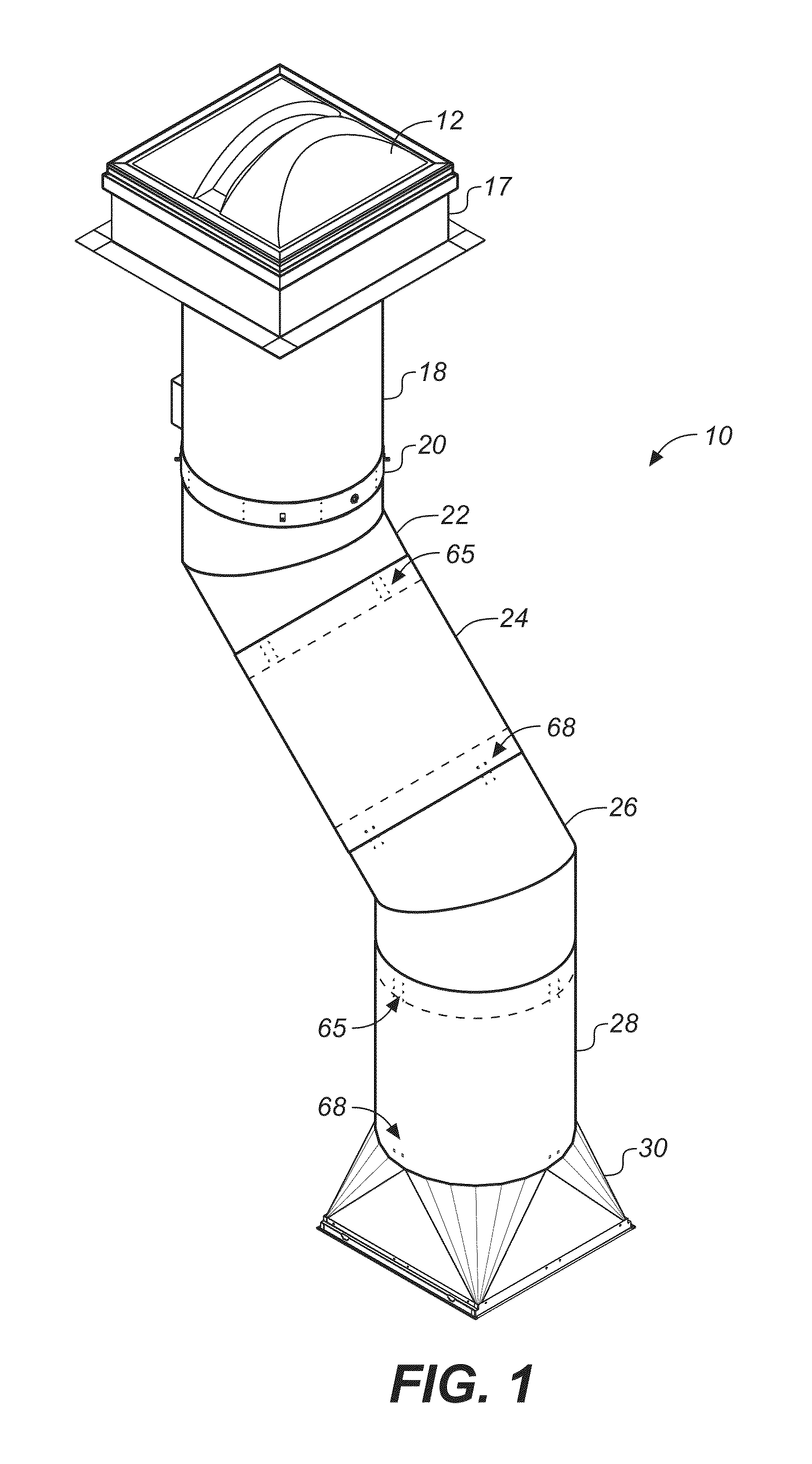
[0007]FIG. 1 is an upper perspective view of an improved tubular daylighting system according to the invention.

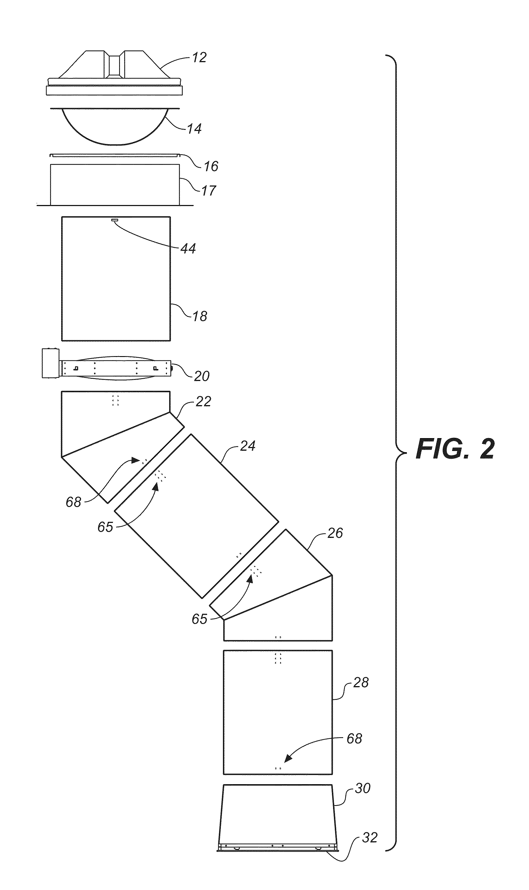
[0008]FIG. 2 is an exploded side elevation system of the improved tubular daylighting system shown in FIG. 1.

[0009]FIG. 2A is a perspective view of the diffuser, transition plate, square curb piece and upper shaft section of the improved tubular daylighting system shown in FIGS. 1 and 2.

[0010]FIG. 3 is an upper perspective view of a skylight of the improved tubular daylighting system shown in FIG. 1.

[0011]FIG. 4 is an upper perspective view of a optic sphere thereof.

[0012]FIG. 5 is an upper perspective view of a square-to-round transition plate thereof.

[0013]FIG. 6 is an upper perspective view of a square curb piece thereof.

[0014]FIG. 7 is an upper perspective view of a tube angle piece thereof.

[0015]FIG. 8 is an upper perspective view of a straight tube section thereof.

[0016]FIG. 9 is an upper perspective view of a light damper thereof.

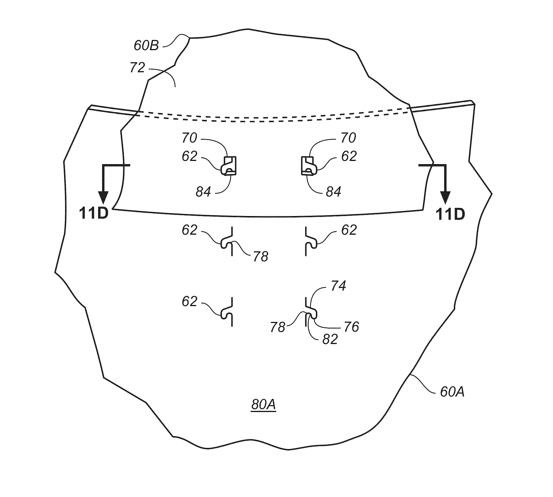
[0017]FIG. 10 is an upper perspective...


PUM


Abstract

An improved tubular daylighting system comprises a plurality of tubular shaft sections connected to a skylight lens for transmitting light through the shaft sections to the interior of a building. Adjoining top and bottom shaft sections have different diameters to enable one to be inserted into the other, the top shaft section having a plurality of tabs, the bottom section having a plurality of slots which register with the tabs of the top shaft section, such that selectively bending the tabs outwardly or inwardly from the shaft wall of the top shaft section through the slots of the bottom shaft section interconnects the top and bottom shaft sections in coaxial alignment. In one embodiment an inverted dome diffuser is mounted below the skylight lens atop the shaft sections to diffuse light entering the shaft sections.

Description

CROSS-REFERENCE TO RELATED APPLICATIONS[0001]This application claims benefit of U.S. Provisional Application No. 61 / 643,171, filed May 4, 2012.BACKGROUND OF THE INVENTION[0002]The present invention generally relates to a skylight system for bringing natural daylight into buildings and more particularly to tubular skylights, sometimes referred to as “tubular daylighting devices,” which use a light tube or pipe for transmitting daylight captured by a skylight on a roof structure down to another region of the building where it is emitted, such as through a false ceiling, into a living space within the building.[0003]Tubular skylight devices are well known and have long been used for bringing daylight down into the interior of buildings having false ceilings. One common problem is that other equipment may create an obstruction in the ceiling space between the roof and ceiling that prevents connecting the light-gathering skylight to a light-emitting panel in a false ceiling using a strai...

Claims


Application Information

Patent Timeline
Patent Type & Authority Patents(United States)
IPC IPC(8): E04D13/03F21S11/00G02B17/00G02B19/00
CPCF21S11/00G02B19/0042E04D2013/034G02B19/0028
Inventor WEAVER, SCOTT
Owner ABL IP HLDG
Why Eureka
Try Eureka