Imaging lens, and portable electronic apparatus including the same

Active Publication Date: 2015-02-10
GENIUS ELECTRONICS OPTICAL CO LTD
View PDF18 Cites 2 Cited by
  • Summary
  • Abstract
  • Description
  • Claims
  • Application Information

AI Technical Summary

Benefits of technology

[0009]Therefore, an object of the present invention is to provide an imaging l

Problems solved by technology

A conventional imaging lens that includes four lens elements is no lo

Method used


Image

  • Imaging lens, and portable electronic apparatus including the same
  • Imaging lens, and portable electronic apparatus including the same
  • Imaging lens, and portable electronic apparatus including the same

Examples


Embodiment Construction

[0049]Before the present invention is described in greater detail, it should be noted that like elements are denoted by the same reference numerals throughout the disclosure.

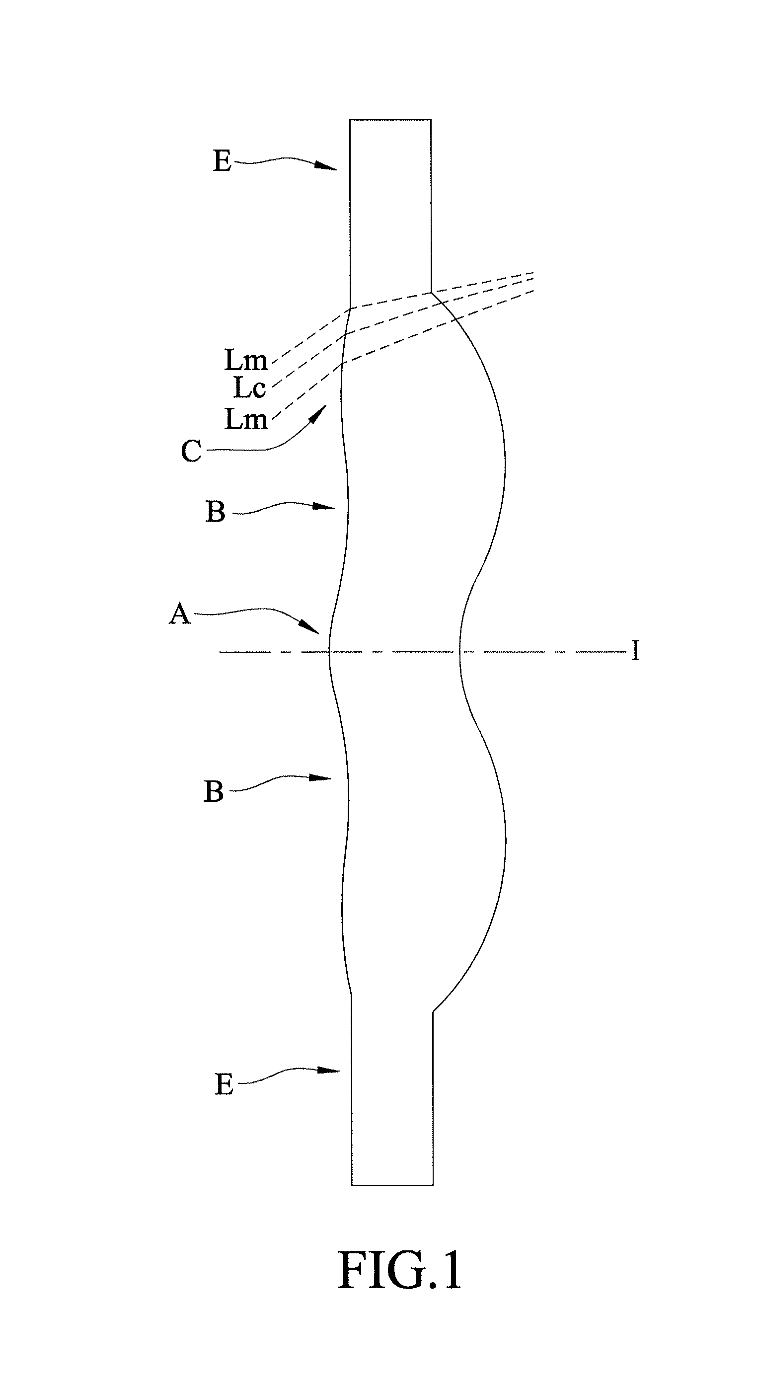
[0050]In the following description, “a lens element has a positive (or negative) refractive power” means the lens element has a positive (or negative) refractive power in a vicinity of an optical axis thereof. “An object-side surface (or image-side surface) has a convex (or concave) portion at a certain area” means that, compared to a radially exterior area adjacent to said certain area, said certain area is more convex (or concave) in a direction parallel to the optical axis. Referring to FIG. 1 as an example, the lens element is radially symmetrical with respect to an optical axis (I) thereof. The object-side surface of the lens element has a convex portion at an area A, a concave portion at an area B, and a convex portion at an area C. This is because the area A is more convex in a direction parallel to the o...


PUM


Abstract

An imaging lens includes a first lens element, a second lens element, an aperture stop, a third lens element, a fourth lens element, and a fifth lens elements arranged from an object side to an image side in the given order. Through designs of surfaces of the lens elements and relevant optical parameters, a short system length of the imaging lens may be achieved while maintaining good optical performance.

Description

CROSS-REFERENCE TO RELATED APPLICATION[0001]This application claims priority to Taiwanese Application No. 102135349, filed on Sep. 30, 2013.BACKGROUND OF THE INVENTION[0002]1. Field of the Invention[0003]The present invention relates to an imaging lens and a portable electronic apparatus including the same.[0004]2. Description of the Related Art[0005]In recent years, as use of portable electronic devices (e.g., mobile phones and digital cameras) becomes ubiquitous, much effort has been put into reducing dimensions of portable electronic devices. Moreover, as dimensions of charged coupled device (CCD) and complementary metal-oxide semiconductor (CMOS) based optical sensors are reduced, dimensions of imaging lenses for use with the optical sensors must be correspondingly reduced without significantly compromising optical performance.[0006]A conventional imaging lens that includes four lens elements is no longer able to fulfill customers' requirements for higher image quality. Developm...

Claims


Application Information

Patent Timeline
IPC IPC(8): G02B3/02G02B13/00
CPCG02B13/0045G02B3/04
Inventor LIAO, CHEN-CHENG
Owner GENIUS ELECTRONICS OPTICAL CO LTD
Why Eureka
Try Eureka