FM antenna structure

An antenna structure, coil antenna technology, applied in resonant antennas, antenna supports/installation devices, loop antennas with ferromagnetic material cores, etc., can solve problems such as long length, and achieve the effect of short length

Inactive Publication Date: 2018-12-28
BS MOVA TECH CO LTD
View PDF5 Cites 0 Cited by
  • Summary
  • Abstract
  • Description
  • Claims
  • Application Information

AI Technical Summary

Problems solved by technology

The antennas disclosed therein are all hollow wire-wound coil antennas inside. Although the energy loss caused by this hollow wire-wound antenna is less than that of the aforementioned magnetic core wire-

Method used


Image

  • FM antenna structure
  • FM antenna structure
  • FM antenna structure

Examples


Embodiment Construction

[0032] In order to have a clearer understanding of the technical solutions, objectives and effects of the present invention, the specific implementation manners of the present invention will now be described with reference to the accompanying drawings.

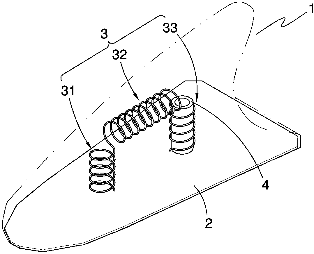
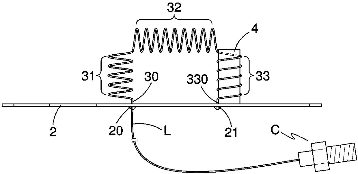
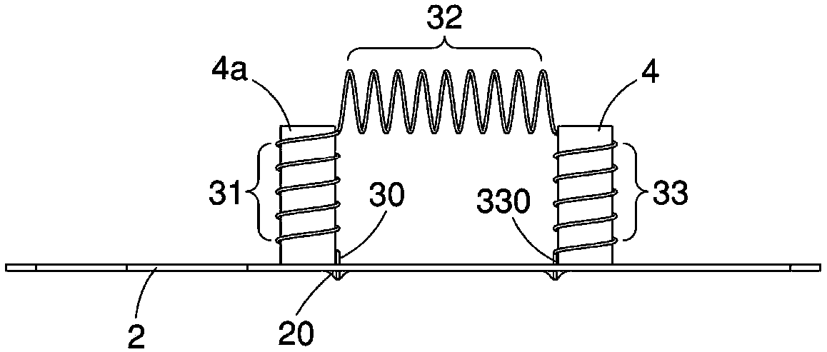
[0033] figure 1 , 2 It shows the first preferred embodiment of the FM antenna structure of the present invention, which is essentially a FM car shark fin antenna for receiving FM signals. In more detail, the FM antenna structure of the present invention includes a shark-fin-shaped housing 1, a circuit board 2 disposed in the shark-fin-shaped housing 1, a wire-wound coil antenna 3 connected to the circuit board 2, and A solid material4. One surface of the circuit board 2 has a conductive pad 20, and the wound coil antenna 3 is used to collect radio signals with a predetermined bandwidth, and in this embodiment is used to collect FM signals. Wherein, a front end 30 of the wire-wound coil antenna 3 is soldered to the conductiv...


PUM


Abstract

The invention discloses an FM antenna structure, which comprises at least one winding coil antenna and at least one solid material. The wire-wound coil antenna has a front end, and the front end is asignal feeding point. The solid material is disposed inside the wound coil antenna and occupies only a portion of the wound coil antenna so that a portion of the space inside the wound coil antenna has the solid material and the remaining space is hollow. The solid material is disposed inside the wound coil antenna and occupies only a portion of the wound coil antenna. Therefore, the invention hasthe advantages of short antenna length, small signal energy loss and easy impedance matching.

Description

technical field [0001] The invention relates to an antenna structure, in particular to a vehicle FM antenna structure. Background technique [0002] The shark fin antenna of known technology is fixed on the top of the car and is electrically connected to the car radio for listening to FM radio programs. The interior of this shark fin antenna has an antenna made of conductive metal. For example, the patent of "Improved Shark Fin Antenna Structure" in Taiwan Announcement M457311 has disclosed that a shark fin antenna includes a circuit board and is welded on the circuit board. A core-wound coil antenna for receiving FM signals. The interior of this core-wound coil antenna is fully occupied by the magnetic core, so much of the received FM signal energy will be absorbed by the magnetic core, resulting in energy loss. [0003] Another example is the antenna structure disclosed in Taiwan Patent No. M297054, which is composed of two upright and side-by-side half-wavelength antenn...

Claims


Application Information

Patent Timeline
IPC IPC(8): H01Q1/14H01Q9/27H01Q7/08
CPCH01Q1/14H01Q7/08H01Q9/27
Inventor 邓圣明池昀蓁
Owner BS MOVA TECH CO LTD
Why Eureka
Try Eureka