A thermal power measuring device

A technology for measuring device and thermal power, applied in the direction of measuring device, measuring heat, calorimeter, etc., can solve the problems of fluctuation, trouble and large volume of output thermal signal of electric bridge, achieve stable thermal power signal and simplify sample loading Process, chemically stable effect

Active Publication Date: 2016-03-23
INST OF CHEM CHINESE ACAD OF SCI
View PDF5 Cites 0 Cited by
  • Summary
  • Abstract
  • Description
  • Claims
  • Application Information

AI Technical Summary

Problems solved by technology

[0003] (1) The reference cell cavity in which the two reference platinum resistance wires in the temperature measurement bridge for measuring thermal power in the device are coaxially distributed in the reaction cell cavity (that is, the area where the two temperature measurement platinum resistance wires are wound) ) on both sides, while the isothermal zone in the constant temperature furnace is a section of space distributed axially around the reaction pool. The temperature of the reference pool may be lower than the reaction pool and is more susceptible to external influences. This uneven axial temperature will cause bridges The output thermal signal fluctuates and thus reduces the measurement accuracy of the entire device
[0004] (2) The temperature-measuring bridge as the core of the device generally inputs a constant voltage signal. Because the output signal of the bridge is proportional to the temperature coefficient of the temperature-measuring resistance, and the coefficient decreases with temperature, the output electrical signal is also Decreases with increasing temperature, which reduces the sensitivity of thermal power measurement devices and increases the error
Because the sample tube is a thin straight tube, and there are multiple accessories fixed on it, resulting in large volume and heavy weight, the process of loading the solid sample into the reaction zone in the tube and fixing it there is more troublesome
[0006] (4) The device only uses ordinary needle valves to control the gas flow during use, resulting in unstable flow and large fluctuations in thermal signals over time
[0007] (5) In this device, the thermal resistance wire used to calibrate the relationship between the thermal power to be measured and the output electrical signal (the quotient of the two is the instrument constant) is wound outside the sample tube, and the heat generated by the current passing through the calibrated thermal resistance wire is not all Heating the anti-cell cavity, part of it will escape outwards, which makes the thermal signal response generated by the actual physical and chemical process in the reaction zone not completely equal to the calibration process, and the thermal power measured by this calibration method will be greater than the actual value

Method used


Image

  • A thermal power measuring device
  • A thermal power measuring device
  • A thermal power measuring device

Examples


Embodiment 1

[0049] Embodiment 1, thermal power measuring device

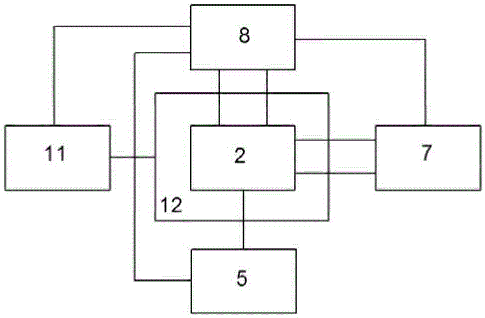
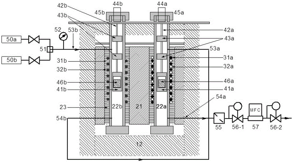
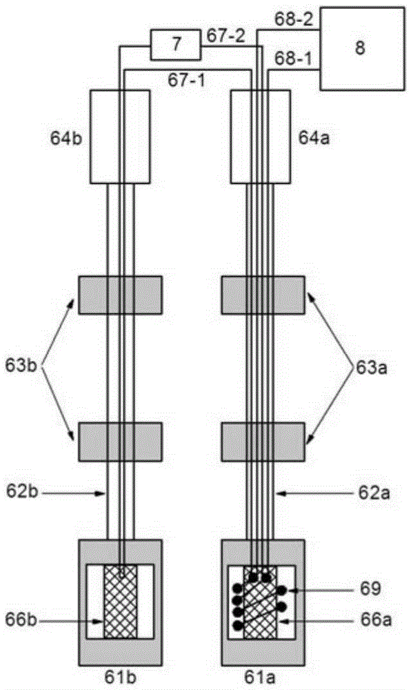
[0050] like figure 1 and figure 2 As shown, the thermal power measurement device provided by the present invention includes a constant temperature system, a calorimeter 2, a thermal measurement system, a reaction system, a gas supply system 5, a thermal calibration system, a program-controlled DC power supply 7, and a data acquisition and control system 8; wherein the constant temperature The system includes a temperature controller 11 and a tube-type constant temperature furnace 12 connected thereto; a calorimeter 2 is provided in the middle of the tube-type constant temperature furnace 12, and the calorimeter 2 includes a cylindrical copper-plated gold-plated soaking block 21. Two parallel and symmetrical cylindrical stainless steel reaction cell chambers 22a and reference cell chambers 22b are arranged in the thermal block 21, and the gap between the reaction cell chamber 22a, the reference cell chamber 22b and the soa...

Embodiment 2

[0059] Application of the thermal power measuring device of embodiment 2 and embodiment 1

[0060] Take the thermal power measurement of the oil sand oxidation process as an example to illustrate the use of the thermal power measuring device provided by the present invention:

[0061] Firstly, input different calibrated thermal power at room temperature to test the linear coefficient between it and the output voltage of the bridge, and this coefficient is the instrument constant of the thermal power measuring device. Change the input voltage signal at different temperatures to ensure that the instrument constant does not change with temperature.

[0062] Figure 4 It is the change of the input voltage signal with temperature when the instrument constant is constant from room temperature to 400°C. The abscissa is the temperature, and the ordinate is the input voltage. It can be seen that the voltage needs to increase with the temperature to ensure that the instrument constant ...


PUM


Abstract

The invention discloses a thermal power measuring device. The thermal power measuring device comprises a constant temperature system, a heat measurement system, a reaction system, a heat calibration system, a gas supply system and a data collecting and control system. The constant temperature system comprises a temperature controller and a constant temperature furnace connected with the temperature controller. A heat measuring cylinder is arranged in the constant temperature furnace. A soaking block is arranged in the heat measuring cylinder. A reaction tank cavity and a reference tank cavity are formed in the soaking block and are symmetrical about the axis of the soaking block. The reaction system comprises a reaction tank sample holder and a reference tank sample holder. The calibration system comprises a reaction tank calibration sample holder and a reference tank calibration sample holder. The reaction tank calibration sample holder and the reference tank calibration sample holder respectively comprise a tubular sample rod and a soaking body II arranged at one end of the tubular sample rod. A ceramic tube is arranged in each soaking body II. A thermal resistor is wound around the ceramic tube of the reaction tank calibration sample holder. The thermal resistor is connected with four leads. The gas supply system comprises a reference gas source and a reaction gas source. The reaction tank cavity and the reference tank cavity are distributed symmetrically in the radial direction, and the influence of axial temperature change of the constant temperature furnace on the measurement of thermal power is offset.

Description

technical field [0001] The invention relates to a thermal power measurement device, which is suitable for thermal power measurement in physical and chemical processes. Background technique [0002] Chinese invention patent CN201110080073.2 discloses a thermal power measuring device. During actual use, it is found that the thermal power measuring device of this invention patent has the following technical problems: [0003] (1) The reference cell cavity in which the two reference platinum resistance wires in the temperature measurement bridge for measuring thermal power in the device are coaxially distributed in the reaction cell cavity (that is, the area where the two temperature measurement platinum resistance wires are wound) ) on both sides, while the isothermal zone in the constant temperature furnace is a section of space distributed axially around the reaction pool. The temperature of the reference pool may be lower than the reaction pool and is more susceptible to ext...

Claims


Application Information

Patent Timeline
Patent Type & Authority Patents(China)
IPC IPC(8): G01K17/00G01N25/20
Inventor 张武寿王龙
Owner INST OF CHEM CHINESE ACAD OF SCI
Why Eureka
Try Eureka