

Phase-transition energy-storage constant-temperature compound infusion tube
A technology of phase change energy storage and infusion tubes, which is applied in the direction of tubes, rigid tubes, pipeline heating/cooling, etc. It can solve the problems of high power consumption and waste of energy, and achieve the effects of not easy to break, easy to manufacture, and good strength
- Summary
- Abstract
- Description
- Claims
- Application Information
AI Technical Summary
Problems solved by technology
Method used
Image

Examples
Embodiment 1
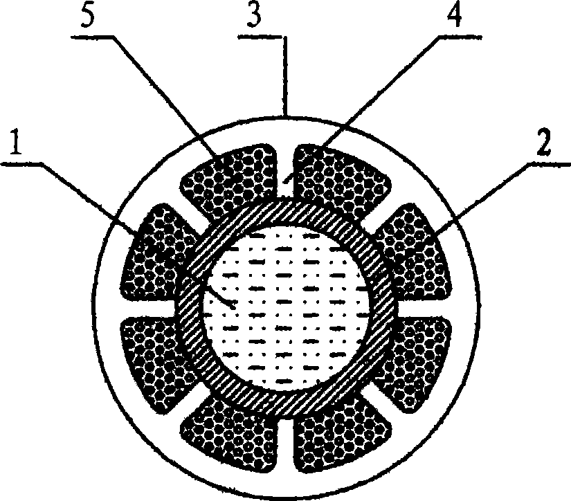
[0033] The structure diagram of the end surface of the outer spoke phase change energy storage constant temperature composite infusion tube is shown in the figure figure 1 As shown, among them: 1 is the high temperature liquid, 2 is the metal infusion tube, 3 is the protective heat preservation pipe, 4 is the radiation plate of the protection heat preservation pipe, the protection heat preservation pipe 3 and the radiation plate 4 of the protection heat preservation pipe are integral, and 5 is the phase change of nano-graphite energy storage material. When manufacturing the composite infusion tube, the metal infusion tube 2 is put into the opening hole formed by the protective heat preservation tube radial plate 4, the metal infusion tube 2 and the end opening of the protective heat preservation tube are closed, and the metal infusion tube 2 and the protective heat preservation tube 3 are closed. In the cavity formed by the protection and insulation tube radial plate 4, the co...
Embodiment 2
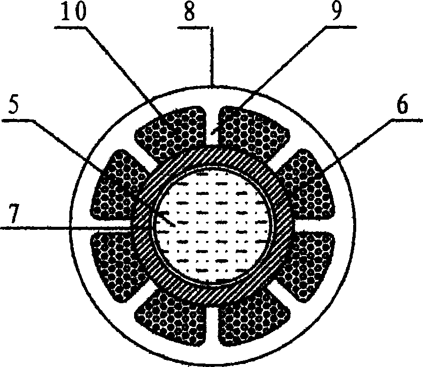
[0036] The structure diagram of the end surface of the outer wheel spoke phase change energy storage constant temperature composite infusion tube lined with fluoroplastic layer is as follows figure 2As shown, wherein: 5 is a high-temperature liquid, 6 is a metal infusion tube, 7 is a fluoroplastic tube, 8 is a protective heat preservation tube, 9 is a protective heat preservation tube radial plate, the protective heat preservation tube 8 and the protective heat preservation tube radial plate are integral, 10 It is a nano graphite phase change energy storage material. When manufacturing the compound infusion tube, firstly, the surface of the fluoroplastic tube 7 is coated with hot melt adhesive, put into the metal infusion tube 8, both ends are closed, and hot steam is passed into the fluoroplastic tube 7, and the fluoroplastic tube 7 is expanded and combined with the hot melt adhesive. Bond together in metal infusion tube 6 lumens. Put the metal infusion tube 6 of the compos...
Embodiment 3
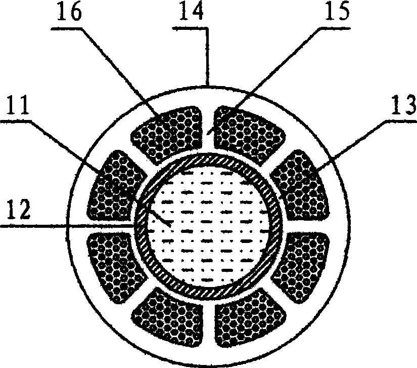
[0039] The structure diagram of the end surface of the overall spoke phase change energy storage constant temperature composite infusion tube is as follows image 3 As shown, wherein: 11 is a high-temperature liquid, 12 is a fluoroplastic infusion tube, 13 is an inner protective insulation tube, 14 is an outer protective insulation tube, 15 is a protective insulation tube radial plate, an inner protective insulation tube 13 and an outer layer The protection insulation pipe 14 is integral with the protection insulation pipe web 15, and 16 is a nano-graphite phase change energy storage material. When manufacturing the composite infusion tube, first, in the cavity formed by the inner layer protective insulation tube 13, the outer layer protective insulation tube 14 and the protective insulation tube web 15, the colloidal nano-graphite phase change energy storage material 16 is poured, and the colloidal nano-graphite phase change energy storage material 16 is poured. After the gra...
PUM
 Abstract
Description
Claims
Application Information