Thermoelectric power source utilizing ambient energy harvesting for remote sensing and transmitting

a technology of remote sensing and transmitting, applied in the manufacture/treatment of thermoelectric devices, thermoelectric devices with peltier/seeback effects, electrical apparatus, etc., can solve the problems of unanticipated capabilities and requirements, device that draws electrical energy from a chemical reaction has a useful life limited by the duration,

Active Publication Date: 2010-11-16
BATTELLE MEMORIAL INST
View PDF84 Cites 27 Cited by
  • Summary
  • Abstract
  • Description
  • Claims
  • Application Information

AI Technical Summary

Benefits of technology

[0006]Accordingly, it is an object of the present invention to provide methods and apparatus for providing reliable power for long periods of time. These and other objects of the present invention are accomplished by taking advantage of temperature differences existing in the environment, and providing devices and techniques to convert these differences in temperature into electrical energy. The present invention in particular relies on the use of techniques and devices to harvest ambient energy in the environment, thereby focusing and concentrating temperature differences that exist in natural and man made environments. Thus, while the present invention is most advantageous in remote and less accessible locations, the concept and operation of the present invention is equally applicable in any environment having at least two regions of different temperature.
[0007]Accordingly, the present invention is a method and apparatus for providing electrical energy to an electrical device wherein the electrical energy is originally generated from temperature differences in an environment having a first and a second temperature region. The first and second temperature regions may, for example, be adjacent features of the natural environment that exhibit a pervasive difference of temperature, such as the ground and the air above the ground or the air inside and outside of heating, air-conditioning or ventilation ducts in buildings. While large temperature differences assist in the generation of electrical energy in a thermoelectric device, one of the several advantages of the present invention is that it allows for the generation of electrical energy in environments having very slight temperature differences. Accordingly, while not meant to be limiting, it is preferred that the temperature difference between said first temperature region and said second temperature region be between 0.5° F. and 100° F., and it is more preferred that the temperature differential between said first temperature region and said second temperature region be between 0.5° F. and 50° F. It should be noted that the present invention is useful beyond the preferred temperature ranges and at all intermediate temperature ranges. It should further be noted that the present invention is operable in applications wherein the relative temperatures of the first and second regions are reversed on occasion, as is the case, for example when soil is the first temperature region and air is the second temperature region, and the two are in a climate wherein the soil tends to be cooler than the air in the summer time, and hotter than the air in the winter time, or vise versa.
[0009]Whatever particular means or combination of means are selected for transmitting ambient energy, the goal remains the same; to gather enough of the energy in the surrounding environment to generate a useful amount of power in the thermoelectric device. Conceptually, a preferred embodiment of the present invention can be envisioned as a thermoelectric device that is placed at the boundary between two regions in the environment that exhibit pervasive differences in temperature. Means for transmitting the ambient energy in either of these regions to opposite sides or ends of the thermoelectric device extend into each of the respective energy regions, thereby amplifying the actual temperature difference experienced by the thermoelectric device, and exaggerating the boundary between the two energy regions.

Problems solved by technology

Advances in electronics have created a variety of devices having heretofore unanticipated capabilities and requirements.
Several options are available for providing power to such devices, such as batteries and solar cells, however, each of these approaches has drawbacks.
While battery technology has advanced tremendously in recent years, any device that draws electrical energy resulting from a chemical reaction has a useful life limited by the duration of the chemical reaction.
Thus, remote applications relying exclusively on batteries are inherently limited by the battery life and reliability.
Environmental factors can hinder the useful life of solar energy sources used in remote locations as well.
Excessive cloud cover and shifting weather patterns can make solar cells unreliable.
Dust and debris deposited on the surface of solar devices by rain or other weather related effects together with normal aging can also degrade the regular operation of these devices.
Due to the drawbacks associated with these and other power technologies, there remains a need for reliable power sources that can operate over long time periods in remote locations.
At present, this vision is impractical because conventional power solutions are either technically inadequate or too expensive.
Fitting every sensor with a battery power supply involves the above noted performance limitations of batteries in addition to the high cost of initial installation and periodic replacement.
The alternative of hard wiring a large number of sensors to a central supply would improve reliability, but would necessarily involve complex circuitry and cost that make this approach economically unviable.
However, the distances across typical thermo electric devices are typically small, that heretofore none have been successfully configured to take advantage of the temperature variation between, for example, the ground below and the air above it.

Method used


Image

  • Thermoelectric power source utilizing ambient energy harvesting for remote sensing and transmitting
  • Thermoelectric power source utilizing ambient energy harvesting for remote sensing and transmitting
  • Thermoelectric power source utilizing ambient energy harvesting for remote sensing and transmitting

Examples


Embodiment Construction

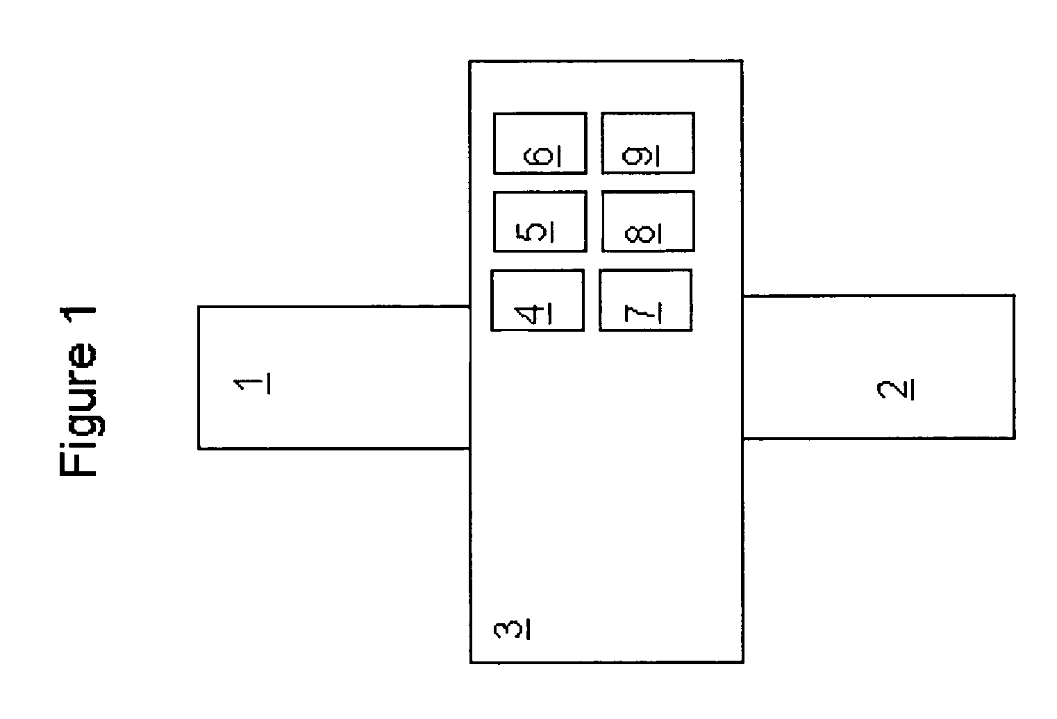
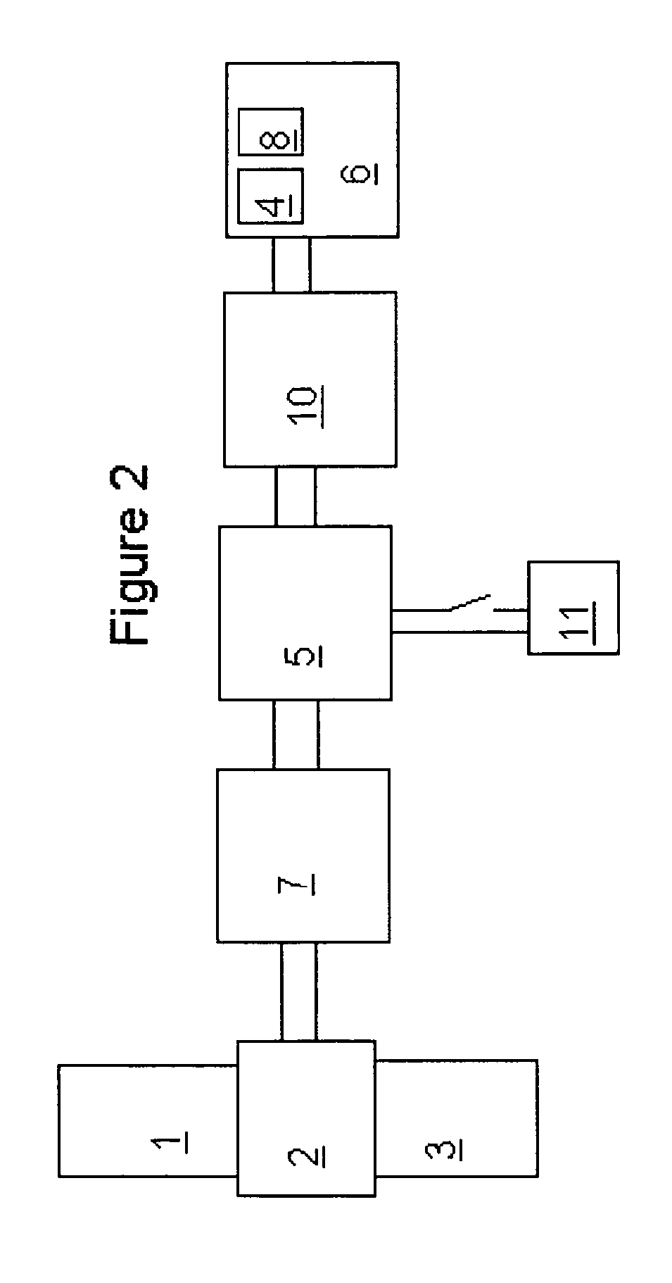
[0018]A series of experiments were conducted to demonstrate the operation of a preferred embodiment of the present invention. The basic circuit configuration in these experiments is shown in FIG. 2. In this circuit, a commercial 40 mm×40 mm bismuth telluride thermoelectric element 2 supplied by MELCOR of Trenton, N.J. was attached to heat pipes 1, 3 supplied by Beckwith Electronics of Fenton, Mo. One of the heat pipes supplied thermal energy from the warmer ambient region to the 40 mm×40 mm hot shoe side of the device. The second heat pipe 3 conducted heat from the corresponding 40 mm×40 mm cold shoe located on the opposite side of the thermoelectric element and dissipated this heat in the colder ambient region. The balance of the circuit consisted of a voltage amplifier 7, a supercapacitor 5, a temperature sensor 4, a microprocessor 8 that managed data acquisition and storage, a voltage regulator 10 and a radio frequency transmitter 6. The voltage amplifier 7 transformed the typica...


PUM


Abstract

A method and apparatus for providing electrical energy to an electrical device wherein the electrical energy is originally generated from temperature differences in an environment having a first and a second temperature region. A thermoelectric device having a first side and a second side wherein the first side is in communication with a means for transmitting ambient thermal energy collected or rejected in the first temperature region and the second side is in communication with the second temperature region thereby producing a temperature gradient across the thermoelectric device and in turn generating an electrical current.

Description

STATEMENT REGARDING FEDERALLY SPONSORED RESEARCH OR DEVELOPMENT[0001]This invention was made with Government support under Contract DE-AC0676RLO1830 awarded by the U.S. Department of Energy. The Government has certain rights in the invention.BACKGROUND OF THE INVENTION[0002]Advances in electronics have created a variety of devices having heretofore unanticipated capabilities and requirements. In many circumstances, these devices present capabilities and requirements that are particularly useful in remote or inaccessible locations where the electrical power necessary to operate the devices is not readily available. For example, remote sensors, such as might be used to measure temperature, pressure, humidity, the presence or movement of vehicles, humans and animals, or other environmental attributes, can easily be configured to acquire and transmit such data to a more accessible location. Several options are available for providing power to such devices, such as batteries and solar ce...

Claims


Application Information

Patent Timeline
Patent Type & Authority Patents(United States)
IPC IPC(8): H01L35/30H01L35/08H01L35/34
CPCH01L35/08H01L35/34H10N10/817H10N10/01
Inventor DESTEESE, JOHN G.OLSEN, LARRY C.
Owner BATTELLE MEMORIAL INST
Why Eureka
Try Eureka