Electric rivet pulling device

An electric riveting device and rivet clip technology are applied in the field of hand-held tools, which can solve the problems of complicated procedures and damage to rivet attachments, and achieve the effects of reducing manufacturing costs, improving riveting work, and improving work efficiency.

Inactive Publication Date: 2015-07-01
翟潇
View PDF6 Cites 0 Cited by
  • Summary
  • Abstract
  • Description
  • Claims
  • Application Information

AI Technical Summary

Problems solved by technology

Although the above method can completely remove the rivet core, the process is complicated, and sometimes careless operation will cause unnecessary damage to the rivet attachment

Method used


Image

  • Electric rivet pulling device
  • Electric rivet pulling device
  • Electric rivet pulling device

Examples


Embodiment 1

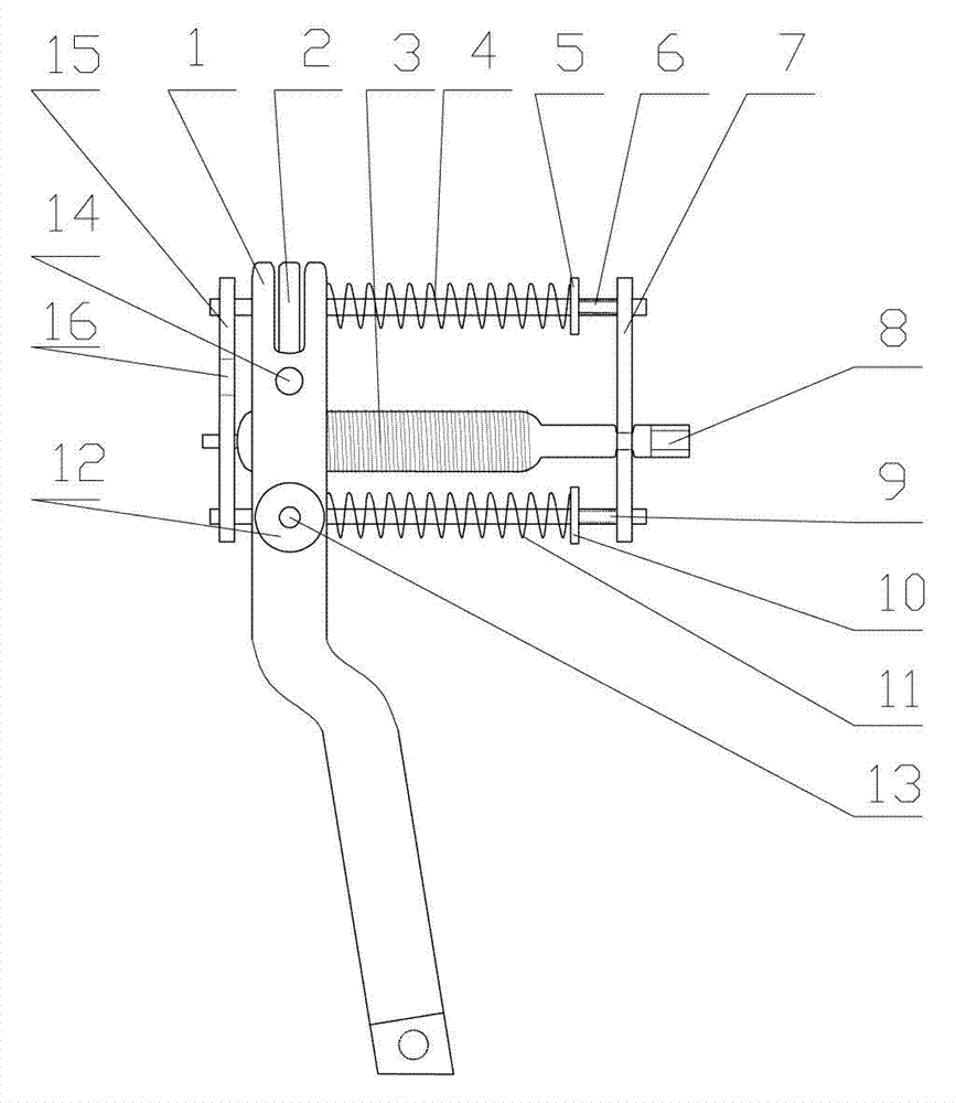
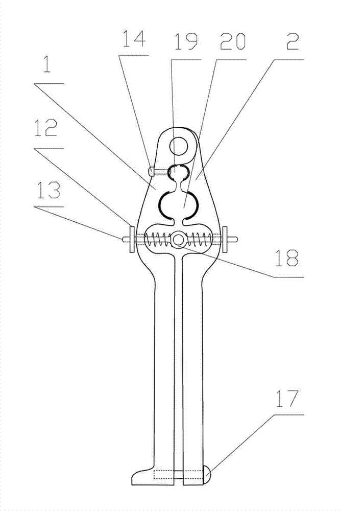
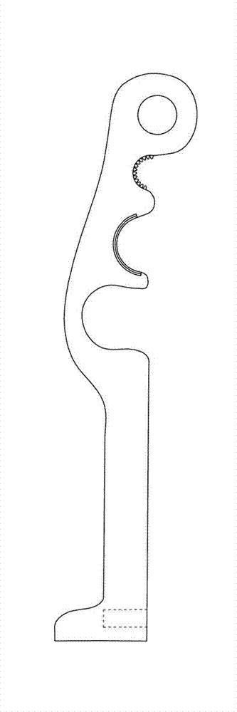
[0024] Such as figure 1 , figure 2 , image 3 , Figure 4 As shown, an electric riveter includes a hinged left handle 1 and a right handle 2, and the upper part of the opposite side of the left handle 1 and the right handle 2 is respectively provided with two arc-shaped grooves, one of which is There are clamping teeth inside, and threads are processed inside the other arc-shaped groove. Two arc-shaped depressions with clamping teeth form the rivet clamping opening 19, and two arc-shaped grooves processed with threads form the screw sleeve. 20; the screw sleeve 20 is internally threaded with a screw 3; the left section of the screw 3 is thicker as a threaded section, the right section is thinner and the right end is designed as a square connector 8 for use with an electric drill. The two ends of screw mandrel are respectively connected with front fixed plate 15 and rear fixed plate 7, and front fixed plate 15 is positioned at handle left side, and rear fixed plate 7 is pos...


PUM


Abstract

The invention relates to an electric rivet pulling device which comprises a left handle and a right handle, wherein the left handle is hinged to the right handle. Two arc grooves are formed in the upper portions of the opposite sides of the left handle and the right handle respectively, clamping teeth are formed in one arc groove, threads are machined in the other arc groove, a rivet clamping opening is formed by the two arc grooves with the clamping teeth, and a lead screw sleeve is formed by two arc grooves with the machined threads. A lead screw is in threaded connection inside the lead screw sleeve. The section on the left side of the lead screw is thick and serves as a thread section, the section on the right side of the lead screw is thin, and the end on the right side of the lead screw is designed into a square connector which is matched with an electric drill for use. The electric rivet pulling device can improve work efficiency by 3-5 times through simple clamping and electric operation. Compared with an old type rivet pulling device, the electric rivet pulling device is lower in manufacturing cost, and meanwhile reduces manufacturing cost of a rivet pulling nail.

Description

technical field [0001] The invention relates to a hand-held tool used in construction and decoration industries, in particular to an electric riveter that can be used in conjunction with an electric drill to remove rivets from their installation positions. Background technique [0002] Blind rivets are a commonly used connection fixture, which has the advantages of firm connection, etc., but the rivet operation is more troublesome. The commonly used method is mainly to use special pliers to clamp the tail of the rivet core and pull it out. There are also pneumatic riveting operations. Although the above method can completely remove the rivet core, the process is complicated, and sometimes careless operation will cause unnecessary damage to the rivet attachment. Contents of the invention [0003] The object of the present invention is to provide an electric riveter used in conjunction with a small electric drill, which can pull out the rivet core conveniently and quickly....

Claims


Application Information

Patent Timeline
Patent Type & Authority Patents(China)
IPC IPC(8): B21J15/50
Inventor 张务谨翟潇
Owner 翟潇
Why Eureka
Try Eureka