Illuminated shelving

a technology of illumination and shelving, applied in the field of shelving systems, can solve the problems of less than optimal lighting for the lower shelves and more difficult to hid

Inactive Publication Date: 2015-03-17
DCI MARKETING
View PDF31 Cites 60 Cited by
  • Summary
  • Abstract
  • Description
  • Claims
  • Application Information

AI Technical Summary

Problems solved by technology

When non-illuminated shelving is used, the upper shelves cast shadows that result in less than optimal lighting for the lower shelves.
Such a solution presented the problem that each light fixture had a conventional plug that needed to be plugged into an outlet.
If the shelving has a broader range of adjustment, it is necessary to provide excess power cord, which is more difficult to hide.

Method used


Image

  • Illuminated shelving
  • Illuminated shelving
  • Illuminated shelving

Examples


Embodiment Construction

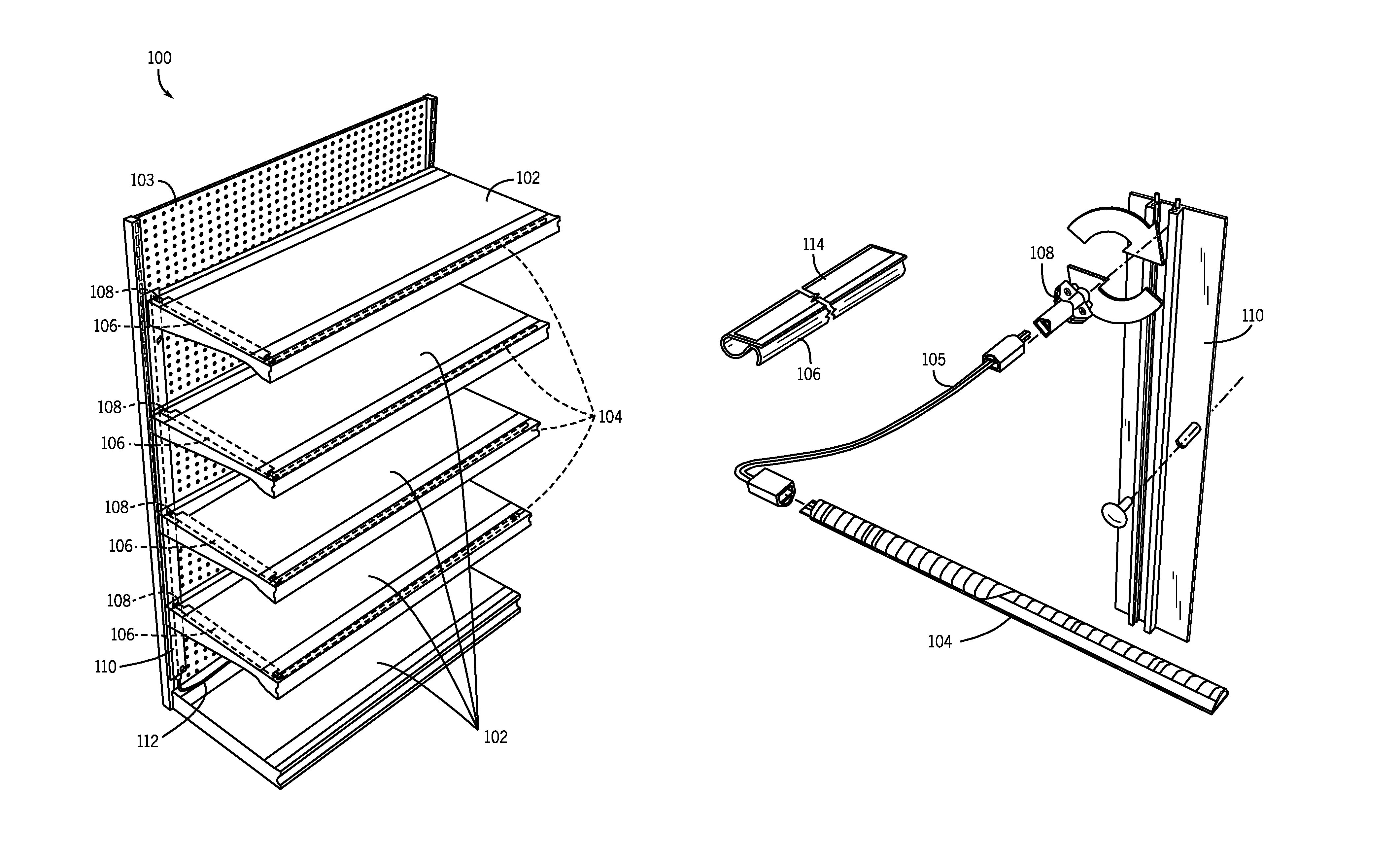
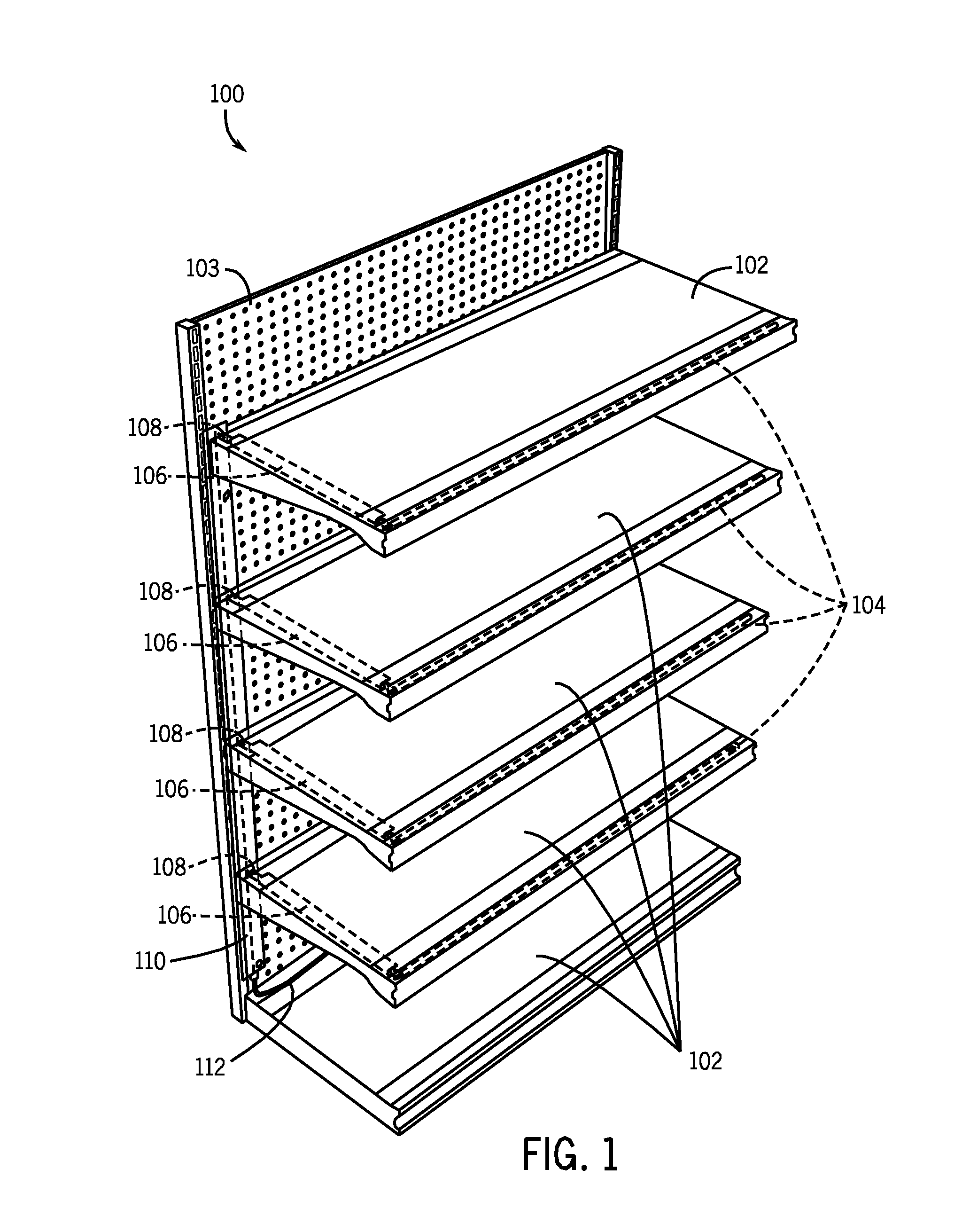
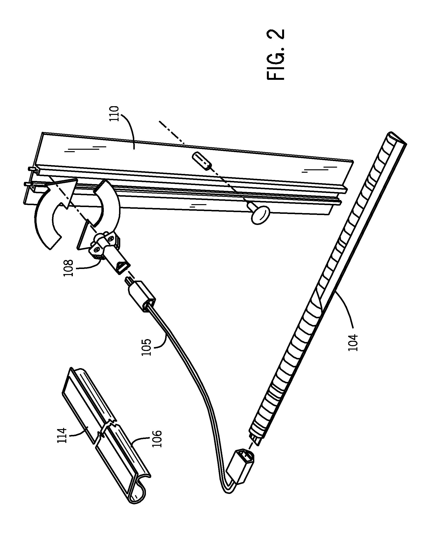
[0015]FIG. 1 is a perspective view of one embodiment of an illuminated shelving system in accordance with the invention. The shelving system 100 includes shelves 102 attached to a shelf support 103, light strips 104, light strip power cords 105, cord channels 106, and plugs 108 that connect to a power strip 110 that, in turn, is connected to a power source by a power cord 112. As shown, the shelves 102 are removably attached to the shelf support 103 and may be adjusted as required by the retailer to provide the proper spacing for displaying products. The light strips 104 are array of light emitting diodes (LED), but other lighting technologies such as halogen, fluorescent, or incandescent lamps may also be used without departing from the present invention. The light strips 104 may provide continuous brightness across the light strip, or may be configured to illuminate only certain portions of the shelf. Such a configuration allows the light strips 104 to provide accent lighting if s...


PUM


Abstract

An illuminated shelving system is provided having light bars attached to the shelves. The light bars are electrically connected to a power strip that conducts electricity from a wall outlet to a plurality of light bars.

Description

CROSS-REFERENCE TO RELATED APPLICATION[0001]This application is based on and claims priority to U.S. Provisional Patent Application No. 61 / 450,420 filed on Mar. 8, 2011, which is incorporated herein by reference in its entirety for all purposes.FIELD OF THE INVENTION[0002]The present invention relates generally to the field of display shelving. More particularly, the present invention relates to a shelving system that incorporates low voltage light fixtures attached to one or more shelves.BACKGROUND[0003]In the retail environment, it is common for merchandise to be displayed on a series of adjustable shelves. Retail display shelving falls into two basic categories: (1) cases where shelves are supported by pins inserted into holes on each side of the case or (2) wall displays where a number of vertically oriented, slotted standards are attached to a wall and brackets having hooks designed to engage the slots support the shelves.[0004]It is desirable to present the merchandise display...

Claims


Application Information

Patent Timeline
Patent Type & Authority Patents(United States)
IPC IPC(8): A41F11/10A47F5/10A47F11/10F21V33/00
CPCA47F5/103F21V33/0012A47F11/10F21Y2103/10F21Y2115/10A47F3/001F21V23/001F21V23/06F21W2131/301F21W2131/405
Inventor WIEMER, JIMBROBT, RYANPERGANDE, JAN
Owner DCI MARKETING
Why Eureka
Try Eureka