Optical fiber management bridge

a technology of optical fiber and management bridge, applied in the field of broadband networks, can solve the problems of limiting the bandwidth and length of the link, affecting the transmission distance of fiber-optic communication systems, and often high cost of multi-mode fibers, etc., and achieves the effect of being effective, economical and durabl

Inactive Publication Date: 2015-04-07
GOOGLE TECH HLDG LLC
View PDF11 Cites 0 Cited by
  • Summary
  • Abstract
  • Description
  • Claims
  • Application Information

AI Technical Summary

Benefits of technology

[0021]An improved bridge provides an optical living hinge for use with optical fibers, such as for use in a broadband network, which is effective, economical and durable. Advantageously, the optical hinge creates a bridge that goes over the hinge-line of a housing which will protect the fiber from getting pinched. The bridge can control the fiber bend radius in a closed node position. Desirably, the optical hinge creates a bridge inside which the fiber can reside safely while the node is opened and closed.
[0023]The optical hinge forms a bridge made of flexible material. This bridge can be installed at the hinge-line of the optical node. The fiber can safely reside in the bridge and still allow the node to open and close properly. The bridge can have a predefined shape when the node is open and when closed will flex and roll inside of the node. The fiber bridge design controls the bend radius of the secured fibers and provides a safe hinge crossing for stress sensitive fiber jumpers. The bridge can be made of polypropylene homopolymer, that when designed as a living-hinge-like part, is rated for over 1 million flexing.
[0026]The improved optical fiber management bridge can comprise an optical hinge which can have a surface(s) secured to the base and top of the housing for hingeably and pivotally connecting the moveable sections. Advantageously, the bridge can have optical fiber-supporting surfaces which can provide one or more optical beds for supporting, cushioning and receiving portions of the optical fibers which are routed and extend between the top and base (bottom) of the housing. The optical fibers can securely lie upon the optical bed in the open and closed positions of the housing. The optical hinge can have an intermediate portion for accommodating safe transition of the optical fibers over the hinge line of the housing. The hinge can comprise of a flexible bridge which can have a predetermined expanded shape when the housing is open and a contracted bent shape when the housing is closed for accommodating flexing and rolling inside the housing.

Problems solved by technology

A multi-mode fiber, however, can cause multimode distortion, which often limits the bandwidth and length of the link.
Multi-mode fibers are often expensive and exhibit higher attenuation.
The transmission distance of a fiber-optic communication system has traditionally been limited by fiber attenuation and fiber distortion.
If an optical fiber is bent too sharply, signals from light traveling in the core of the fiber can actually escape through the cladding and be lost.
Such requirements present design difficulties in terms of creating a flexible and / or moveable on electrical signal path that can survive repeated bending, flexing, translation or other movement.
Presently, there is no solution in the market place to protect optical fibers as they cross the hinge-line of a HFC optical node.
The problem is that when these optical modules are installed in the base side of the node, then the fiber needs to cross what is called the hinge-line of the node.
This is the area where the node opens and closes and in this area the fiber has high risk of getting pinched.
This arrangement still has the potential for pinched wires and stress on termination connectors.
In still other conventional nodes and hubs, different types of plastic spiral wrap and holders are used to secure cables crossing the hinge, but these more rigid solutions have been a major source of customer complaints due to connector stress and intermittent connections.

Method used


Image

  • Optical fiber management bridge
  • Optical fiber management bridge
  • Optical fiber management bridge

Examples


Embodiment Construction

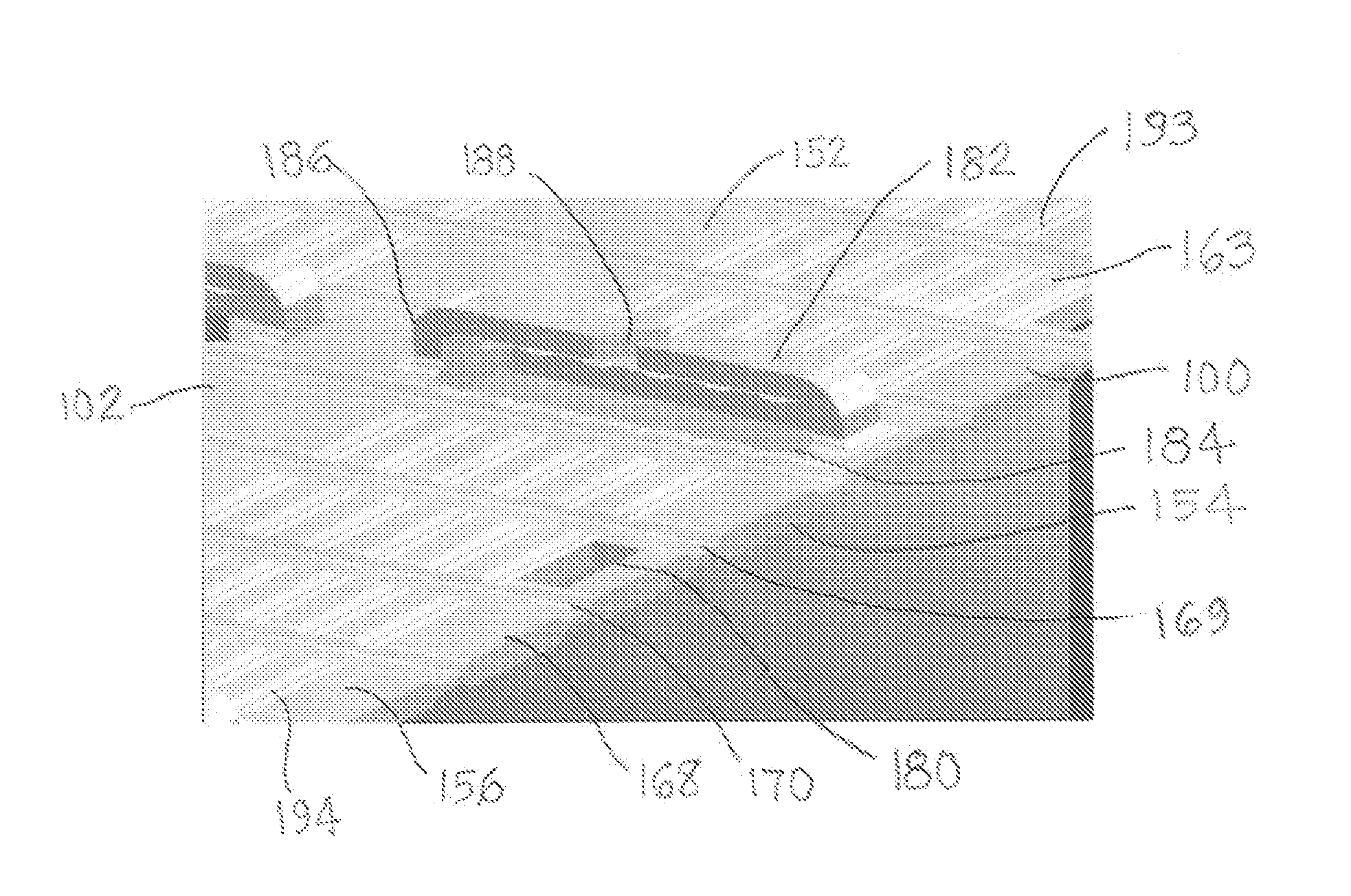
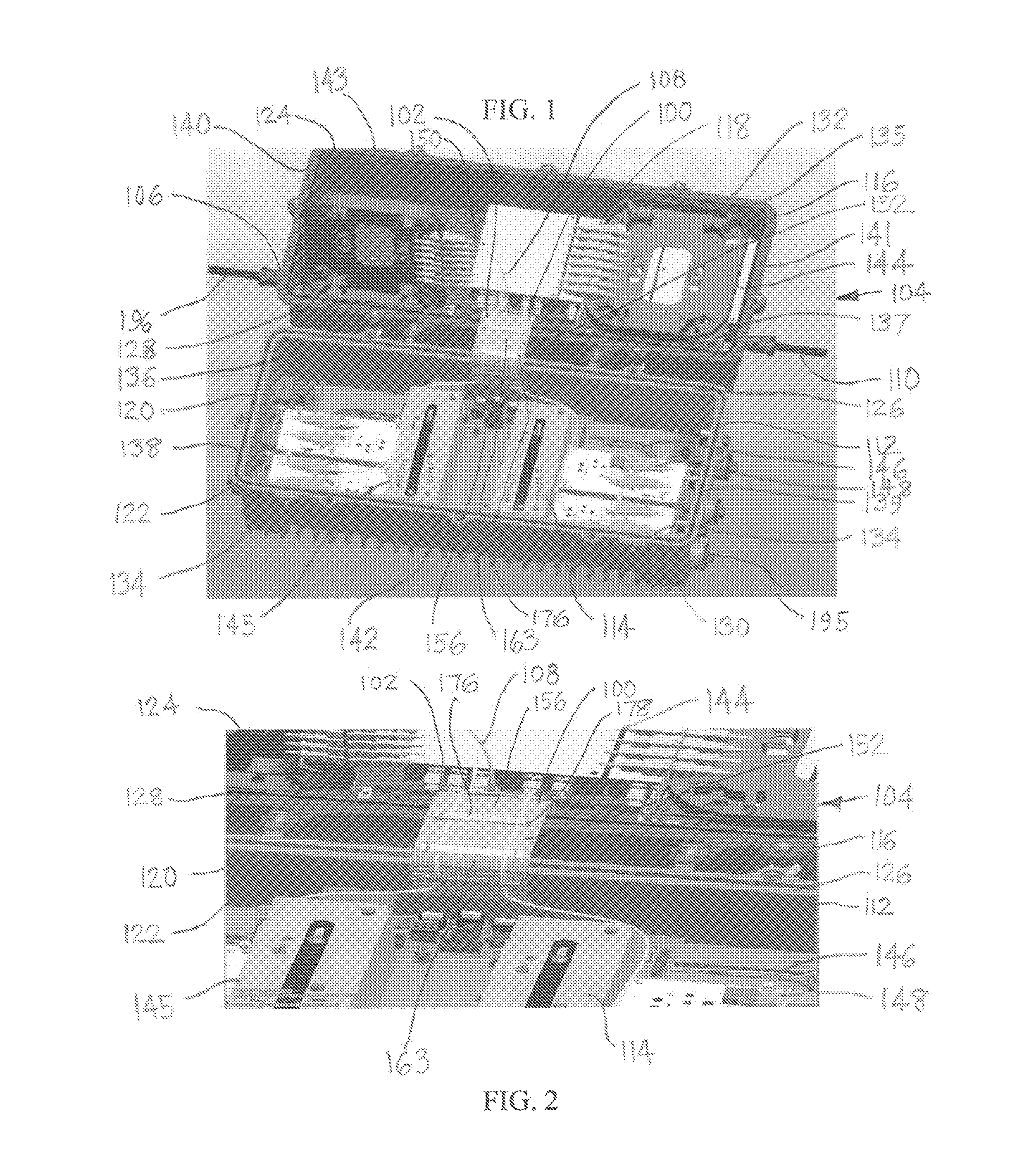
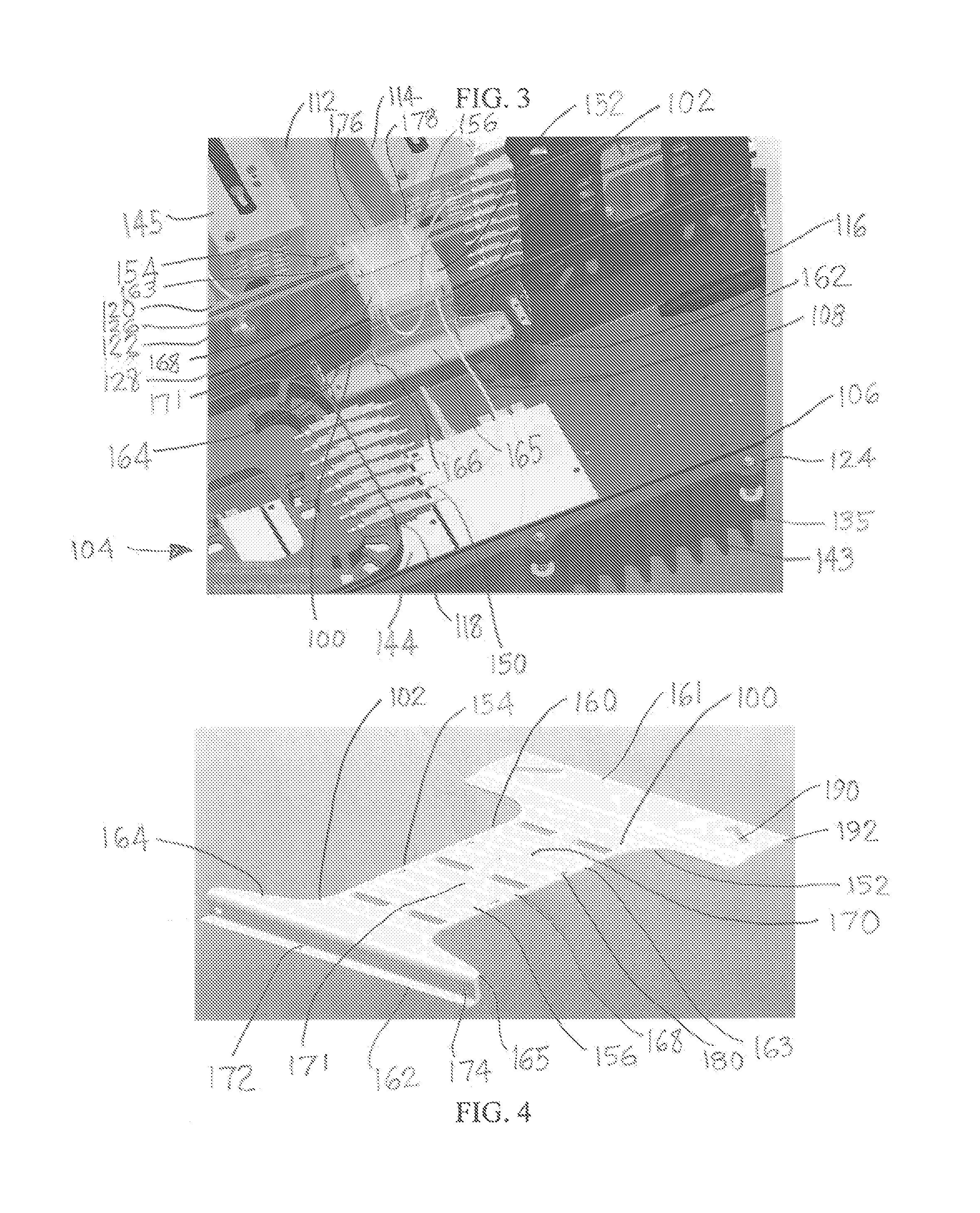
[0038]As shown in FIGS. 1-6 in the drawings, an optical fiber management bridge 100 can provide an optical hinge assembly 102 for use with a broadband network 104 comprising a hybrid fiber-coaxial (HFC) broadband access network (BAN) 106 with optical fibers 108 and coaxial cables 110 for providing digital communications, such as: digital television, high definition television (HDTV), digital video, digital video streaming, video on demand (VOD), data transmission, internet communications, radio frequency (RF) communications, telephone communications, computer communications, telecommunications, or combinations of any of the preceding. The optical fibers can comprise: single mode optical fibers, multiple mode optical fibers, fiber optic cables, fiber jumpers, or combinations of any of the preceding optical fibers.

[0039]The BAN can include a HFC optical module 112 (FIGS. 1-3) which can provide an electronics communications device with an electronics package (e-pack) 114 in a container...


PUM


Abstract

An improved optical fiber management bridge 100 can comprise an optical hinge 152 for an electronics communications device 112 which is especially useful for a broadband network 104. The electronics communications device can have a housing 120 for enclosing an electronics package 114 comprising at least one optical module 118 and optical fibers 108. The optical bridge can have optical surfaces 156 for supporting portions of the optical fibers 108 which are routed and extend between the top 128 and base 122 of the housing 120. The optical bridge can have an intermediate portion 163 for accommodating safe transition of the optical fibers 108 over the hinge line 129 of the housing 120.

Description

BACKGROUND[0001]1. Field of the Disclosure[0002]The disclosure relates in general to broadband networks and, more particularly, to a bridge for use with optical fibers in a broadband network.[0003]2. Background Art[0004]Fiber optic communications are a method of transmitting information by sending pulses of light through an optical fiber. The light forms an electromagnetic carrier wave that is modulated to carry information. Fiber optics communications are useful in broadband networks for telecommunications, data transmission, internet communications, high definition (HD) television, digital video streaming, video on demand (VOD) and other communications.[0005]Due to much lower attenuation and interference, optical fibers provide many advantages over existing copper wire in long-distance and high-demand applications. Because of its advantages over electrical transmission, optical fibers have largely replaced copper wire in networks.[0006]Fiber optic communications can include: trans...

Claims


Application Information

Patent Timeline
Patent Type & Authority Patents(United States)
IPC IPC(8): G02B6/00G02B6/46H04N21/61G02B6/26
CPCG02B6/26G02B6/4447G02B6/445
Inventor RATHOD, VIPUL D.CONROY, DENNIS P.SWIFT, JAMIE J.THIBEAULT, DAVID M.WEISS, THOMAS M.
Owner GOOGLE TECH HLDG LLC
Why Eureka
Try Eureka