Digital electronic system for automatic shut off and turn on of electrical and gas operated appliances

a digital electronic system and automatic shut-off technology, applied in the direction of gaseous heating fuel, fire alarms, stoves or ranges, etc., can solve the problem of not specifically revealing the unique features and electrical circuitry of electrical circuits, and achieve the effect of avoiding a potential kitchen fire or fir

Active Publication Date: 2015-05-12
MILE HIGH HLDG LLC
View PDF17 Cites 17 Cited by
  • Summary
  • Abstract
  • Description
  • Claims
  • Application Information

AI Technical Summary

Benefits of technology

[0007]In view of the foregoing, it is a primary objective of the subject invention to provide a digital electronic system that is responsive to an audio alarm from a smoke detector, carbon monoxide detector and similar ala

Problems solved by technology

This prior art patent doesn't specifically disclose the unique features and electrical circuitry used in th

Method used


Image

  • Digital electronic system for automatic shut off and turn on of electrical and gas operated appliances
  • Digital electronic system for automatic shut off and turn on of electrical and gas operated appliances
  • Digital electronic system for automatic shut off and turn on of electrical and gas operated appliances

Examples


Embodiment Construction

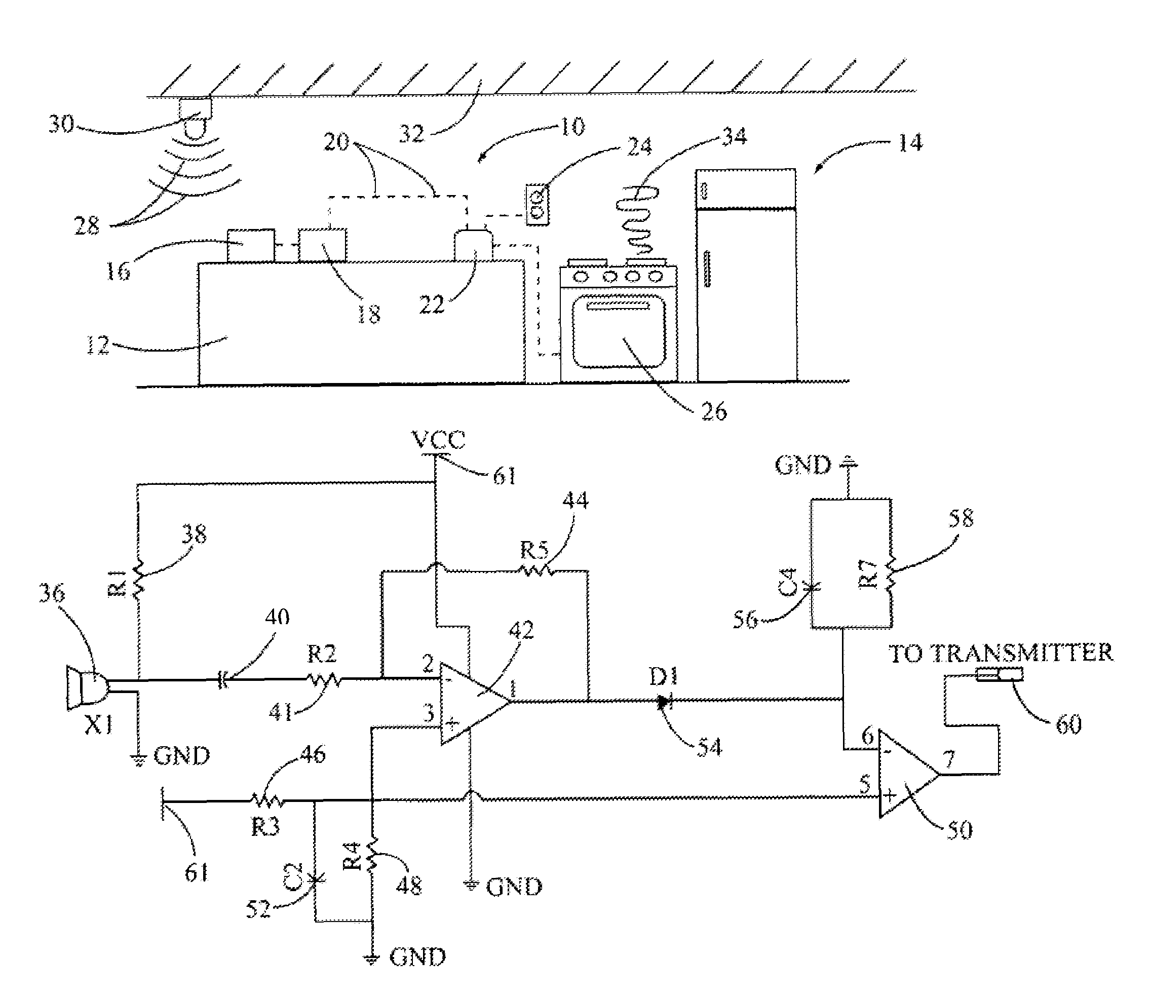
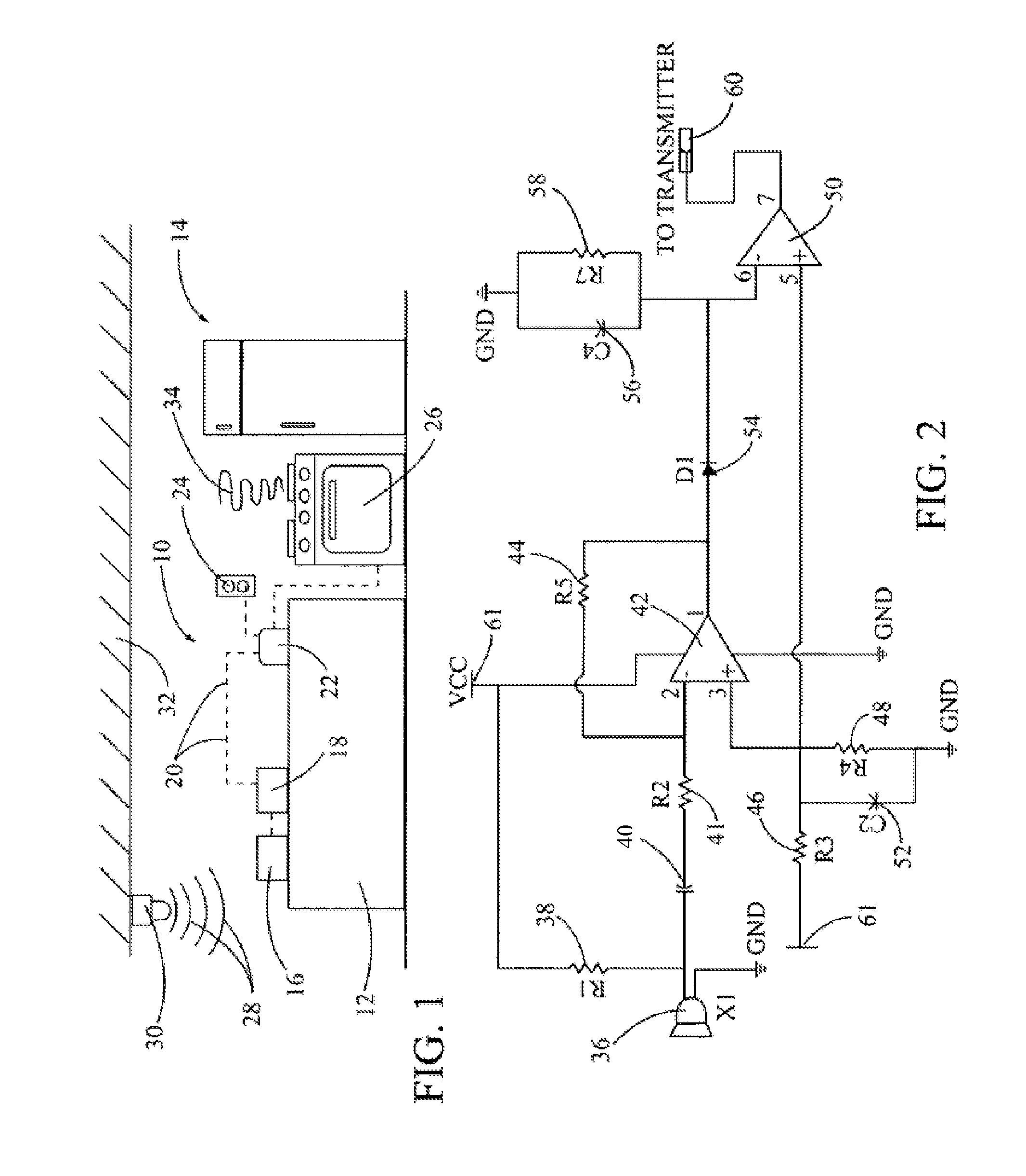
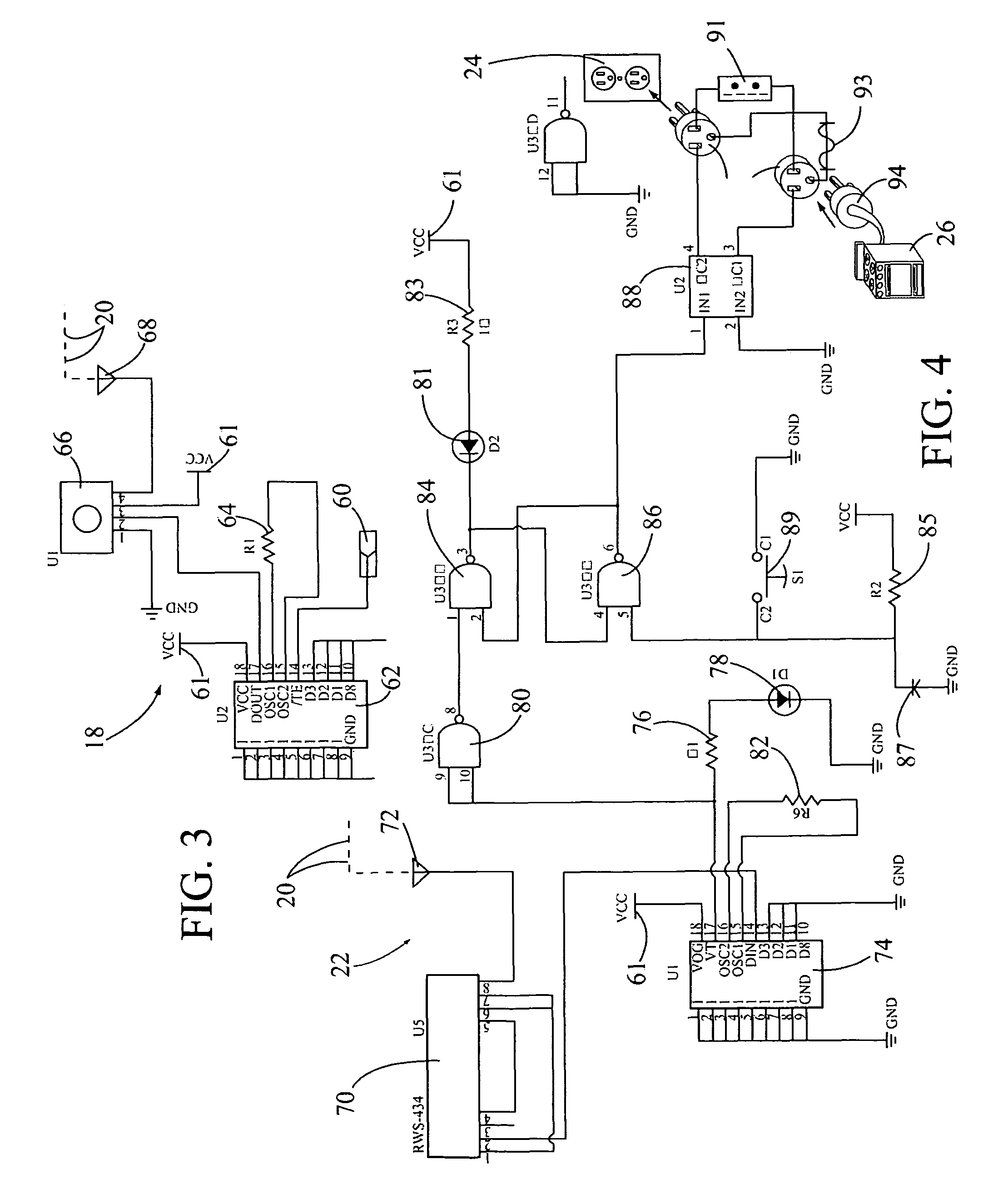
[0024]In FIG. 1, a front view of the subject digital electronic system is illustrated and having general reference numeral 10. In this application, the electronic system 10 is shown received on top of a kitchen cabinet 12 in a kitchen 14. The electronic system 10 broadly includes a microphone and amplifier comparator circuit 16 connected to a radio frequency transmitter and encoder circuit 18. The transmitter and encoder circuit 18 is used for outputting a digital radio frequency signal 20, shown in dashed lines, to a receiver and decoder circuit 22. The receiver and decoder circuit 22 is connected to a wall outlet power source 24, next to a kitchen stove 26.

[0025]In this drawing, the microphone and amplifier comparator circuit 16 is shown receiving an audio alarm 28 from a smoke detector 30 mounted in a ceiling 32 of the kitchen 14. While the smoke detector 30 is discussed herein, the subject electronic system 10 will work equally well with a carbon monoxide detector and similar al...


PUM


Abstract

A digital electronic system used for receiving an audio alarm from a smoke detector, a carbon monoxide detector and like detectors. The system amplifies and converts the alarm to a digital encoded radio frequency signal for shutting off power to a kitchen appliance. The system includes a microphone and an amplifier connected to a comparator circuit. This circuit provides for outputting a logic 0 or logic 1 and outputs a logic 1, in the form of the digital radio frequency signal, if an audio alarm is received. The comparator circuit is connected to a transmitter and encoder circuit, which receives the frequency signal and transmits it to a radio frequency receiver and decoder circuit. This circuit then decodes the signal and disconnects the power to the appliance.

Description

[0001]This application is a continuation-in-part patent application based on an earlier filed non-provisional application, having a title “System for Automatic Shut Off of Electrical Circuits, Ser. No. 12 / 072,506, filed on Feb. 25, 2008 now abandoned, by the subject inventor. Application Ser. No. 12 / 072,506 claims the benefit of an earlier filed provisional patent application Ser. No. 60 / 903,744, filed on Feb. 26, 2007, by the subject inventor.BACKGROUND OF THE INVENTION[0002](a) Field of the Invention[0003]This invention relates to a system used for turning “on” and shutting “off” an electrical circuit to an electrical appliance or a gas appliance. The electrical circuit is adapted for use in a home or an office building and is identified by a brand name “Smart Switch™ System”. The subject invention can be used to control specific circuits such as kitchen appliances, space heaters, furnaces, clothes dryers, Christmas tree lights, and other electrically operated or gas operated appl...

Claims


Application Information

Patent Timeline
IPC IPC(8): G08B1/08F24C3/00F24C7/00G08B17/00G08B17/10
CPCG08B17/00G08B17/10F24C3/00F24C7/00G08B1/08F24C3/126F24C7/08F24C1/02
Inventor HAYNES, MICHAEL LEROY
Owner MILE HIGH HLDG LLC
Why Eureka
Try Eureka