Supercharge Your Innovation With Domain-Expert AI Agents!

Radio communication antenna and radio communication device

a radio communication device and communication antenna technology, applied in simultaneous aerial operations, antennas, antenna feed intermediates, etc., can solve problems such as difficulty in applying typical dipole antennas to broadband communications

Inactive Publication Date: 2015-06-16
ELECTRONICS & TELECOMM RES INST
View PDF13 Cites 0 Cited by
  • Summary
  • Abstract
  • Description
  • Claims
  • Application Information

AI Technical Summary

Problems solved by technology

However, it is difficult to apply the typical dipole antenna to broadband communications.

Method used


Image

  • Radio communication antenna and radio communication device
  • Radio communication antenna and radio communication device
  • Radio communication antenna and radio communication device

Examples


Embodiment Construction

[0024]Preferred embodiments of the inventive concept will be described below in more detail with reference to the accompanying drawings. The present invention may, however, be embodied in different forms and should not be constructed as limited to the embodiments set forth herein. Rather, these embodiments are provided so that this disclosure will be thorough and complete, and will fully convey the scope of the present invention to those skilled in the art.

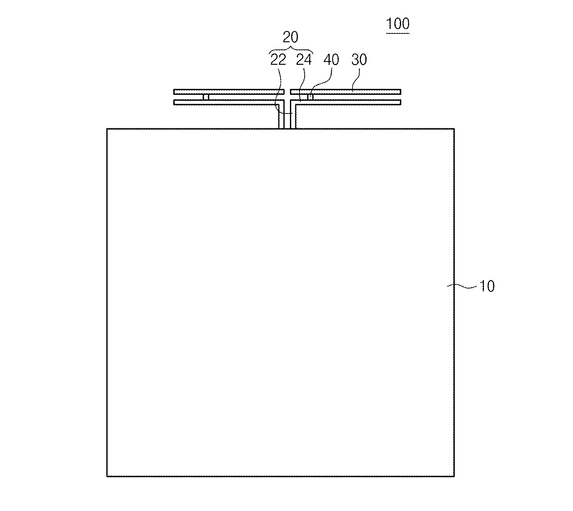
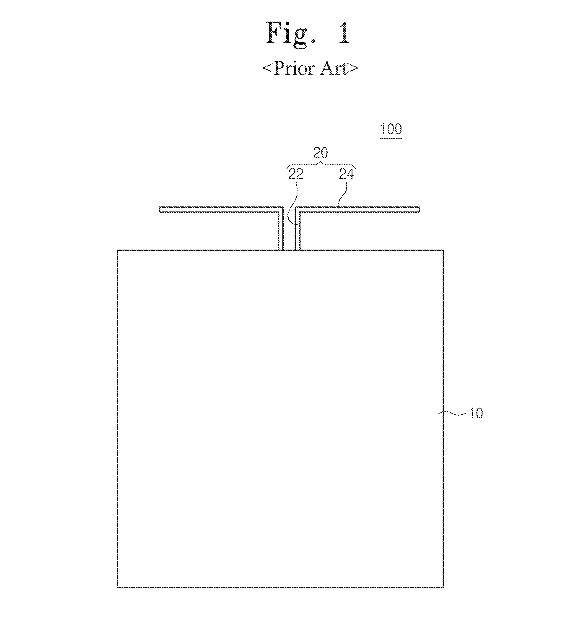
[0025]FIG. 1 is a diagram illustrating a typical radio communication antenna 100.

[0026]Referring to FIG. 1, the typical radio communication antenna 100 may include a substrate 10 and first conductive wires 20. The substrate 10 may be formed of a plastic material. The first conductive wires 20 may include a plurality of vertical conductive wires 22 and a plurality of horizontal conductive wires 24. The vertical conductive wires 22 and the horizontal conductive wires 24 may be symmetrical to each other so as to configure a dipole an...


PUM


Abstract

The present invention relates to a radio communication antenna and a radio communication device including the same. The radio communication antenna of the present invention includes first conductive wires extending in opposite directions with respect to a first direction on a substrate to form a dipole antenna, second conductive wires separated from the first conductive wires to be parallel with the first conductive wires, and stubs connected between the first conductive wires and the second conductive wires in a second direction intersecting with the first direction.

Description

CROSS-REFERENCE TO RELATED APPLICATIONS[0001]This U.S. non-provisional patent application claims priority under 35 U.S.C. §119 of Korean Patent Application Nos. 10-2012-0105916, filed on Sep. 24, 2012, and 10-2013-0028125, filed on Mar. 15, 2013, the entire contents of which are hereby incorporated by reference.BACKGROUND OF THE INVENTION[0002]The present invention disclosed herein relates to a radio communication antenna and a radio communication device, and more particularly, to a dipole antenna and a radio communication antenna including the dipole antenna.[0003]In a radio communication system, without an additional signal propagation medium such as a conductive wire or an optical fiber, signals are transmitted and received through the atmosphere to perform communication. There are radio communication technologies such as amplitude modulation (AM), frequency modulation (FM), phase modulation (PM), amplitude shift keying (ASK), frequency shift keying (FSK), phase shift keying (PSK...

Claims


Application Information

Patent Timeline
Patent Type & Authority Patents(United States)
IPC IPC(8): H01Q9/16H01Q9/06H01Q5/15
CPCH01Q9/16H01Q5/378H01Q5/48H01Q9/065
Inventor LEE, SANG SEOKAHN, SEONGDEOKKOO, JAE BON
Owner ELECTRONICS & TELECOMM RES INST
Features
  • R&D
  • Intellectual Property
  • Life Sciences
  • Materials
  • Tech Scout
  • Unparalleled Data Quality
  • Higher Quality Content
  • 60% Fewer Hallucinations
Learn More