
Track pad

a track pad and track technology, applied in endless track vehicles, vehicles, transportation and packaging, etc., can solve the problems of increasing the tendency of strand material carried up and around the sprocket or idler and reduce the tendency of strand material to become entangled in the roller frame. , the effect of reducing the tendency of strand material

Active Publication Date: 2015-08-11
FREEMAN ERNIE
View PDF37 Cites 6 Cited by
  • Summary
  • Abstract
  • Description
  • Claims
  • Application Information

AI Technical Summary

Benefits of technology

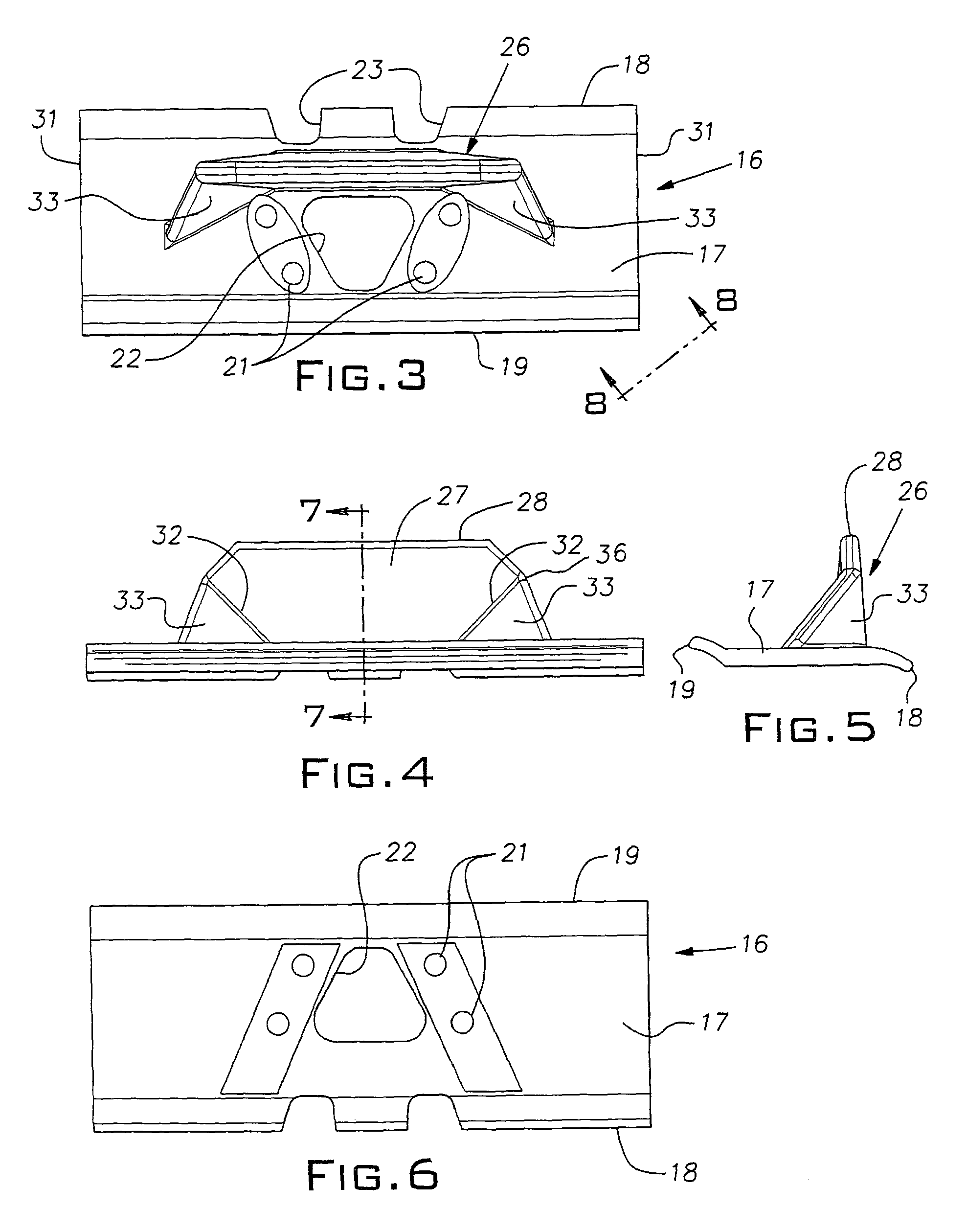
[0004]The invention provides a track pad for a crawler with a unique grouser construction that, surprisingly, reduces or delays destructive build-up of debris in a crawler roller frame when operating in a landfill environment. Additionally, the track pad of the invention advantageously improves traction, compaction, and lateral stability or grip.
[0006]The reason or reasons for the surprising ability of the track pad to reduce fouling of the roller frames is not fully understood. It is believed that the laterally inward spacing of the grouser, possibly in combination with its high rise and / or oblique side portion gussets, reduces the tendency of strand material to be dragged up from the surface onto the upper region of the track. Strand material carried up and around a sprocket or idler appears to have an increased tendency to become entangled in a roller frame.
[0007]In addition to reducing the rate of debris build-up when operating in a landfill, the track pads greatly improve the lateral stability of a tractor enabling it to traverse slopes in directions perpendicular or with a vector component perpendicular to the slope direction. The track pads do not adversely affect the mobility of a crawler and their configuration avoids eccentric loading of the track guides.

Problems solved by technology

Strand material carried up and around a sprocket or idler appears to have an increased tendency to become entangled in a roller frame.

Method used


Image

  • Track pad
  • Track pad
  • Track pad

Examples


Embodiment Construction

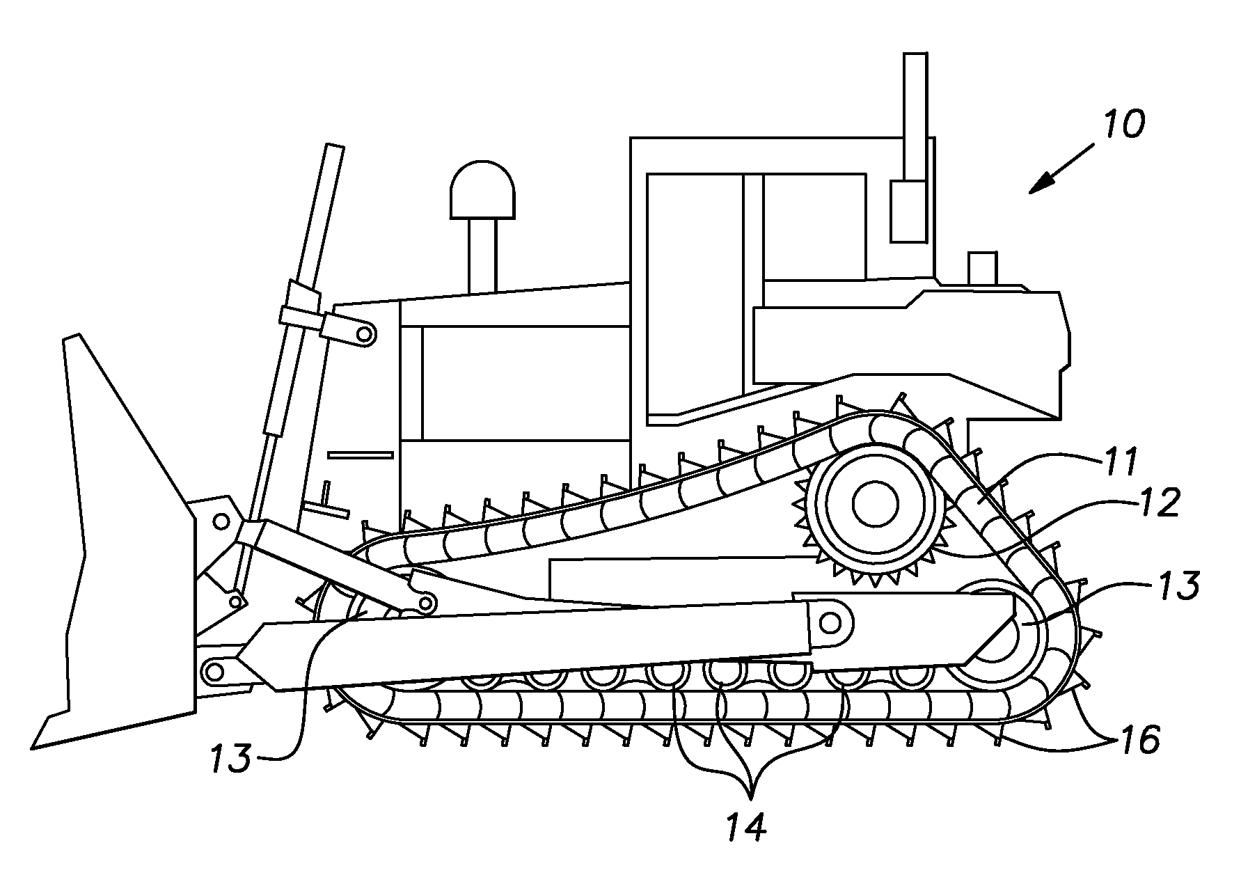
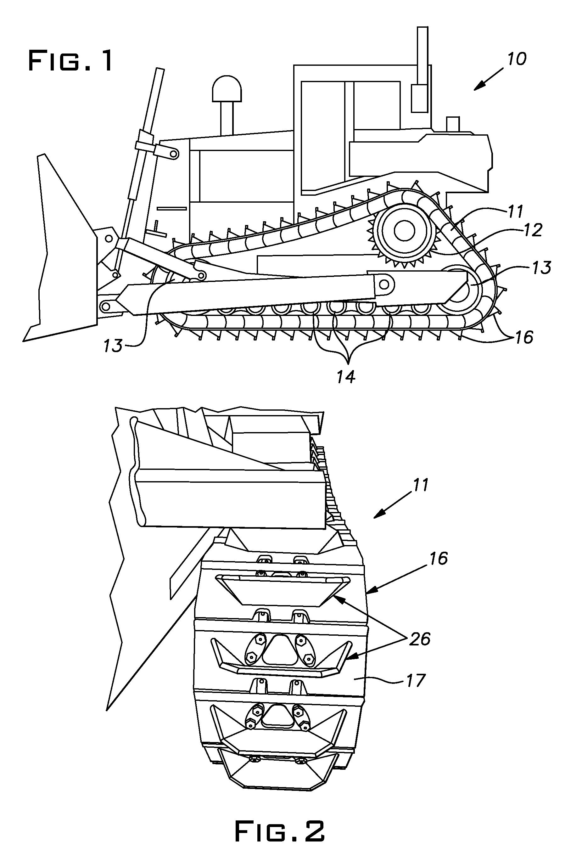
[0016]FIG. 1 illustrates a typical crawler or track machine 10; specifically, the machine illustrated is a model D8R “High Drive” design manufactured by Caterpillar, Inc. It will be understood that the invention is applicable to essentially any track machine, for example, of different size, design, purpose and / or manufacturer. The machine 10 is supported by and carried by an endless track 11 on each side. Each track 11 is trained around a drive sprocket 12 and idlers 13. A lower reach of the track 11 underlies a series of rollers 14 which reduce friction during movement of the track.

[0017]Typically, the track 11 comprises steel links pivotally joined together with pins and steel pads or shoes 16. Customarily, each link has an associated pad 16 bolted to it. The tracks 11, sprockets 12, idlers 13, rollers 14 and related structures are collectively referred to as the roller frames. Conventionally, the track pads 16 are identical to one another. In FIGS. 3-8, the track pad 16 of the in...


PUM


Abstract

A track pad for a crawler, especially operating in a landfill, having a generally rectangular base plate with holes for attachment to a track chain link, the base plate having front, rear and side edges, a high rise grouser on the base plate, the grouser projecting from the base plate a distance substantially greater than conventional grousers, the grouser having a central portion with the general configuration of a plate with an edge distal from the base plate, the central portion being generally laterally centered on the base plate, the grouser being devoid of areas projecting significantly from the base plate adjacent the side edges of the base plate.

Description

BACKGROUND OF THE INVENTION[0001]The invention relates to improvements in tracks for crawler machines and, in particular to an improved track pad for bulldozers operating in landfills and other difficult terrain.PRIOR ART[0002]Crawler or track machines are commonly embodied as bulldozers with a front blade used to push material and / or establish a grade. These machines are used in landfills for dozing and compacting debris and for grading cover material. The surface of a landfill can be difficult to cross or climb with any land vehicle including a crawler since the surface typically comprises loose non-cohesive material of widely diverse physical characteristics. Landfill materials are notoriously destructive to the external rotating and sliding parts of a vehicle's propulsion system.[0003]In a crawler or track machine, debris can wrap around or otherwise develop a drag on moving parts ultimately causing destruction of these parts and / or related seals and bearings. Strands of materia...

Claims


Application Information

Patent Timeline
Patent Type & Authority Patents(United States)
IPC IPC(8): B62D55/26B62D55/075B62D55/28
CPCB62D55/075B62D55/28
Inventor FREEMAN, ERNIE
Owner FREEMAN ERNIE
Learn More