Liquid ejecting head and liquid ejecting apparatus

a liquid ejecting head and liquid ejecting technology, which is applied in the direction of spraying apparatus, spraying nozzles, printing, etc., can solve the problems of poor energy efficiency applied to the piezoelectric element, and achieve the effect of high-efficiency liquid discharging properties

Active Publication Date: 2015-09-22
SEIKO EPSON CORP
View PDF6 Cites 1 Cited by
  • Summary
  • Abstract
  • Description
  • Claims
  • Application Information

AI Technical Summary

Benefits of technology

[0010]An advantage of some aspects of the invention is to provide a liquid ejecting head and a liquid ejecting apparatus having highly-efficient liquid discharging properties which are realized by efficiently displacing the diaphragm to discharge liquid.

Problems solved by technology

Thus, there is a problem in that efficiency of energy applied to the piezoelectric element is poor, compared to the displacement amount due to the piezoelectric element.

Method used


Image

  • Liquid ejecting head and liquid ejecting apparatus
  • Liquid ejecting head and liquid ejecting apparatus
  • Liquid ejecting head and liquid ejecting apparatus

Examples


embodiment 1

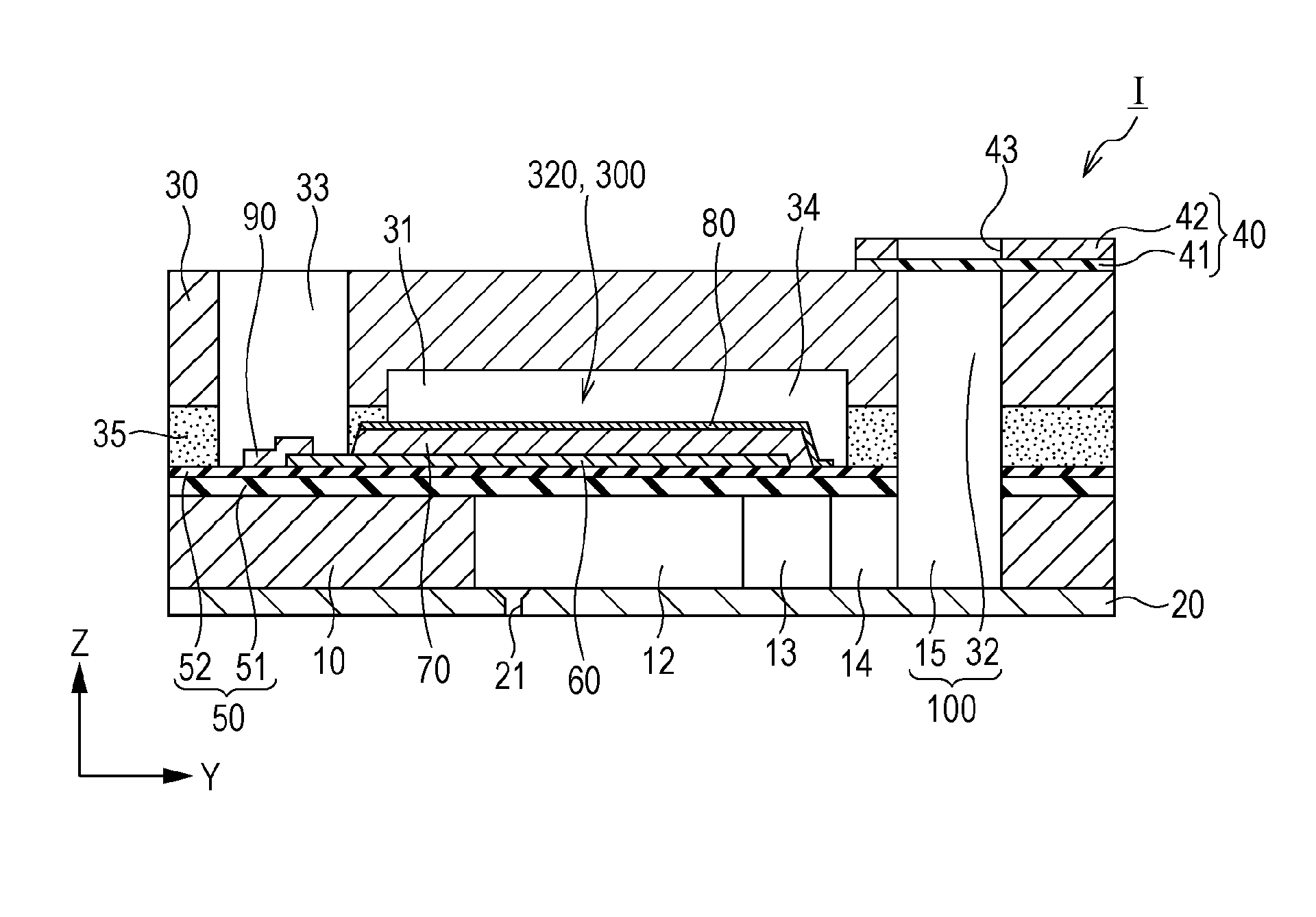
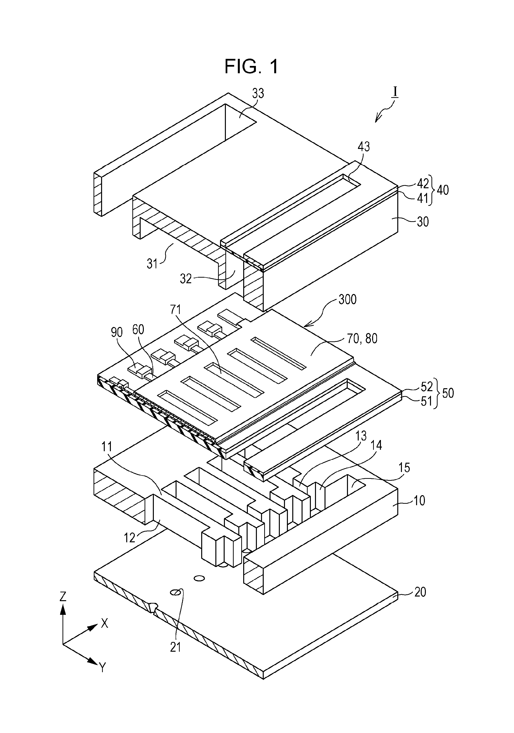
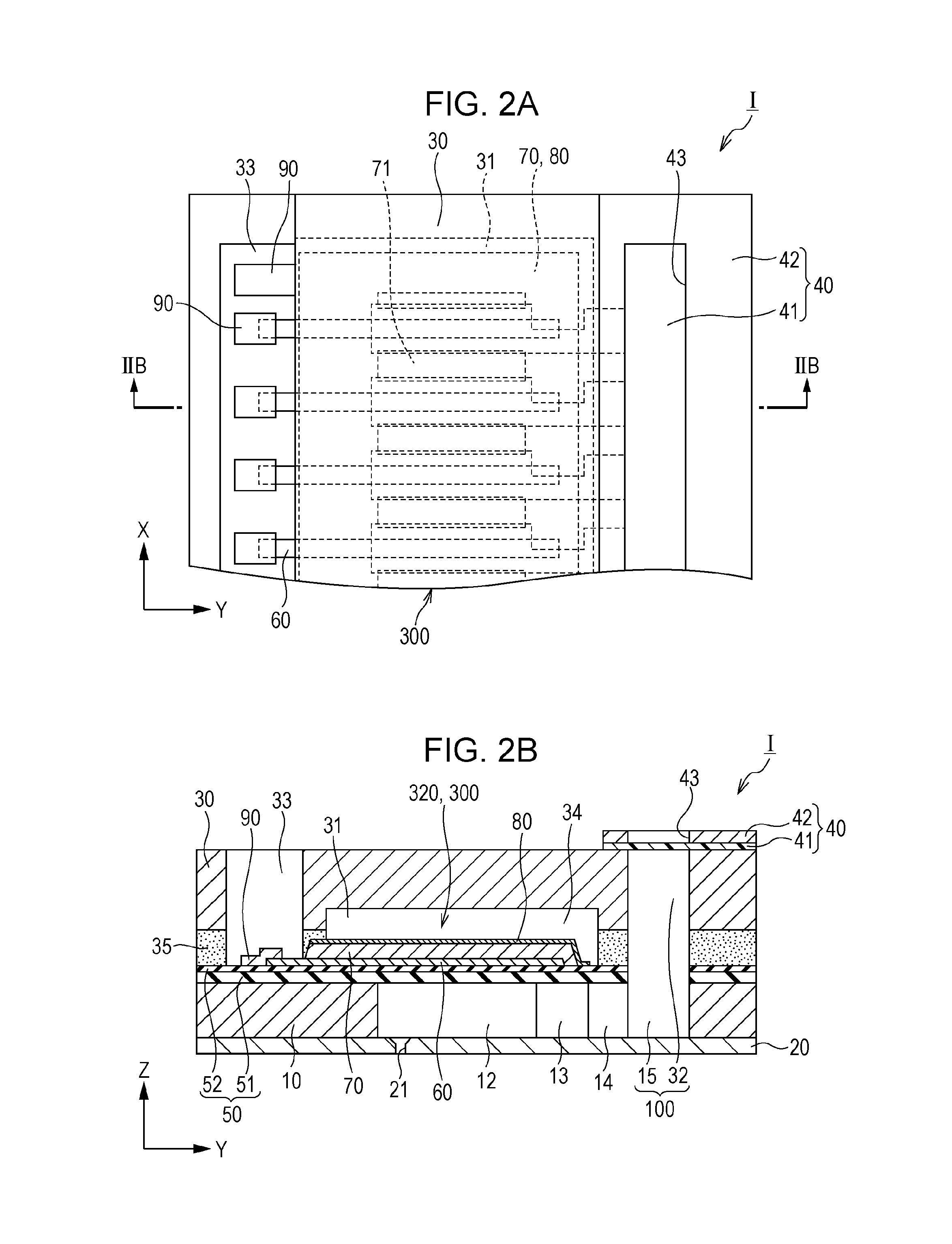
[0033]FIG. 1 is a perspective view of an ink jet type recording head as an example of a liquid ejecting head according to Embodiment 1 of the invention. FIGS. 2A and 2B are a plan view and a cross-sectional view of the ink jet type recording head.

[0034]An ink jet type recording head I according to Embodiment 1 includes a flow-path forming substrate 10, as illustrated in drawings. Pressure generation chambers 12 which are portioned by a plurality of partition walls 11 are formed in the flow-path forming substrate 10. The pressure generation chambers 12 are aligned in a direction in which a plurality of nozzle openings 21 through which ink is discharged are aligned. Hereinafter, this direction is referred to as an alignment direction of the pressure generation chambers 12 or a first direction X. In addition, a direction which is perpendicular to the first direction X in a plane of the flow-path forming substrate 10 is set to be a second direction Y. Furthermore, a direction which is p...

embodiment 2

[0100]The sealed space 34 according to Embodiment 1 is formed by joining the flow-path forming substrate 10 to the protection substrate 30 using the adhesive agent 35. However, the aspect of the sealed space 34 is not limited thereto. To improve a sealability of the sealed space, a sealed space may be formed by applying a direct joining method using a metallic member, not using the adhesive agent 35.

[0101]FIG. 9 is an exploded perspective view of an ink jet type recording head according to Embodiment 2. FIG. 10 is a cross-sectional view of the ink jet type recording head according to Embodiment 2. FIG. 11 is a cross-sectional view of principal portions of the ink jet type recording head according to Embodiment 2.

[0102]An ink jet type recording head II as an example of a liquid ejecting head according to Embodiment 2 includes a plurality of members, such as a head main body 111 and a case member 140, as illustrated in FIGS. 9 to 11. The plurality of members are joined to each other. ...


PUM


Abstract

A liquid ejecting head includes a flow-path forming substrate including pressure generation chambers that communicate with nozzle openings through which ink is ejected, a piezoelectric element that applies a pressure to the pressure generation chambers via a diaphragm, and a protection substrate that forms a sealed space for sealing the piezoelectric element, in which a pressure in the sealed space is adjusted such that the diaphragm is drawn up to the piezoelectric element side and an initial bent position of the diaphragm is adjusted.

Description

BACKGROUND[0001]1. Technical Field[0002]The present invention relates to a liquid ejecting head and a liquid ejecting apparatus and, particularly, relates to an ink jet type recording head and an ink jet type recording apparatus which eject ink as liquid.[0003]2. Related Art[0004]Recently, a liquid ejecting head in which a pressure of liquid in a pressure generation chamber is changed by an actuator device, such as a piezoelectric element, and thus the liquid droplets is ejected through nozzles communicating with the pressure chamber has been known. An ink jet type recording head which ejects ink droplets as liquid droplets is a representative example of the liquid ejecting head described above.[0005]The ink jet type recording head includes a piezoelectric element on one surface side of a flow-path forming substrate in which a pressure generation chamber communicating with nozzle openings is provided. In the ink jet type recording head, a diaphragm is deformed by driving the piezoel...

Claims


Application Information

Patent Timeline
Patent Type & Authority Patents(United States)
IPC IPC(8): B05B1/08B41J2/14
CPCB41J2/14233B41J2002/14241B41J2002/14419B41J2002/14491
Inventor HIRAI, EIJU
Owner SEIKO EPSON CORP
Why Eureka
Try Eureka