
Clamp-on fork lift attachment with stabilizer bar

a technology of stabilizer bar and fork lift, which is applied in the direction of lifting devices, mechanical machines/dredgers, constructions, etc., can solve the problems of not being able to handle larger loads, not always available on job sites, etc., and achieve the effect of adding rigidity

Active Publication Date: 2015-12-22
WERNER CO
View PDF32 Cites 3 Cited by
  • Summary
  • Abstract
  • Description
  • Claims
  • Application Information

AI Technical Summary

Benefits of technology

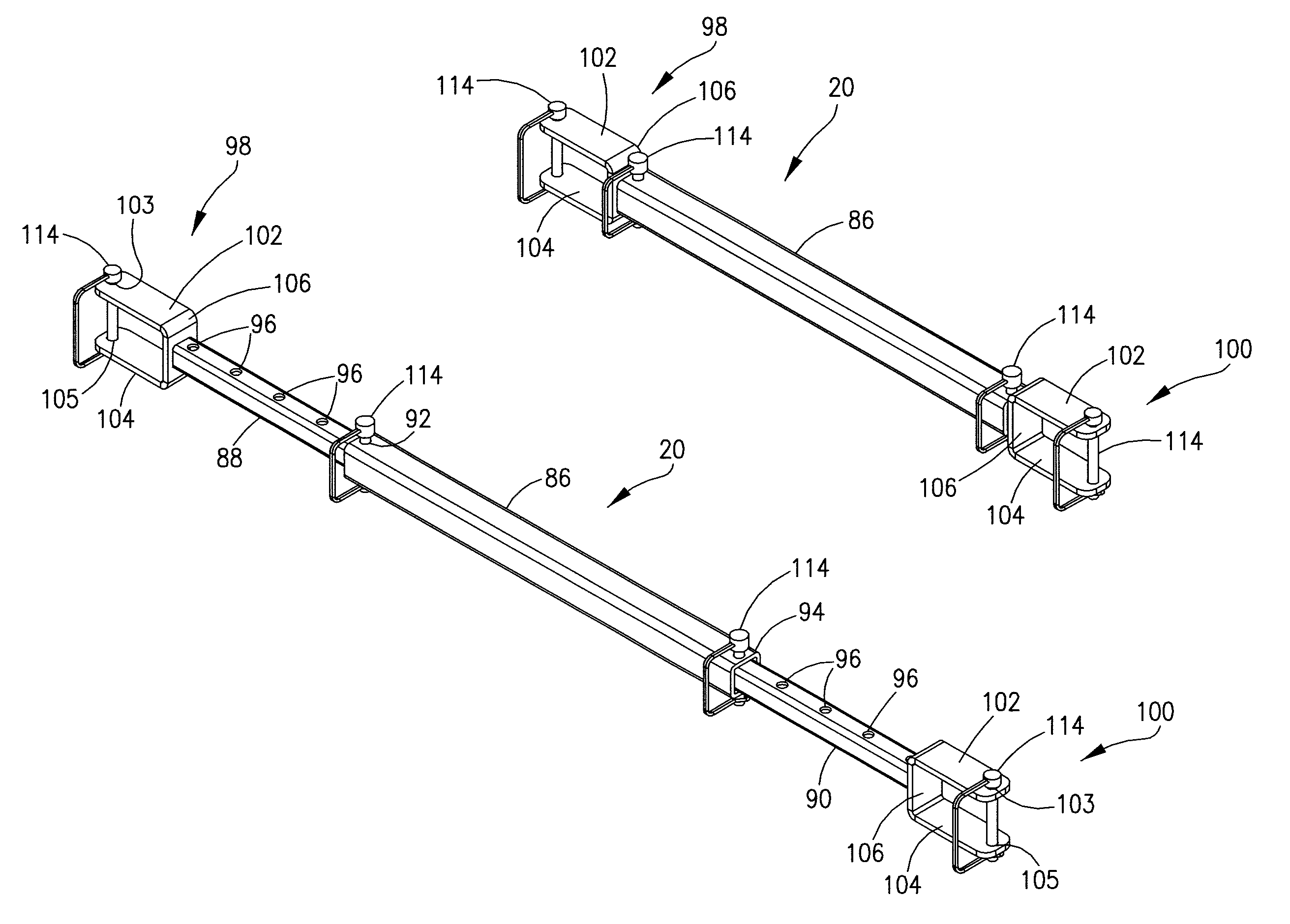
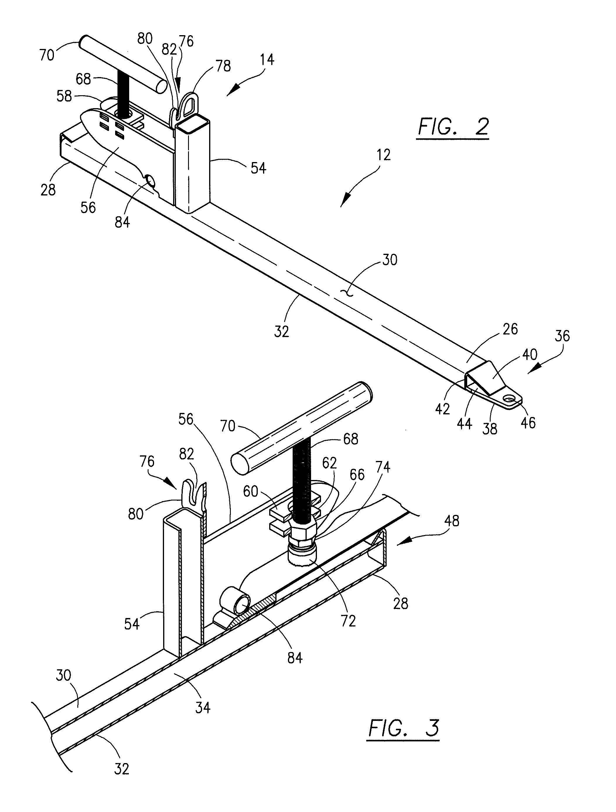
[0005]In one presently preferred embodiment, the attachment of this invention may include a pair of spaced tines each having a lifting plate mounted at the forward end, a leveling indicator mounted at the rearward end and a clamping device with a tie-down element. The lifting plate and tie-down element provide structure where chains, cable, rope or the like may be attached to secure or stabilize objects placed on the tines, and / or to assist in lifting items with the tines. The leveling indicator is mounted in a position on each tine so that it extends beneath the blade portion of the loader bucket and assists in maintaining the tines in a parallel, level orientation relative to the loader bucket.

Problems solved by technology

While dedicated fork lifts of the type described above are effective and useful in a variety of applications, they are not always available on job sites and many do not have the size or lifting capacity to handle larger loads.

Method used


Image

  • Clamp-on fork lift attachment with stabilizer bar
  • Clamp-on fork lift attachment with stabilizer bar
  • Clamp-on fork lift attachment with stabilizer bar

Examples


Embodiment Construction

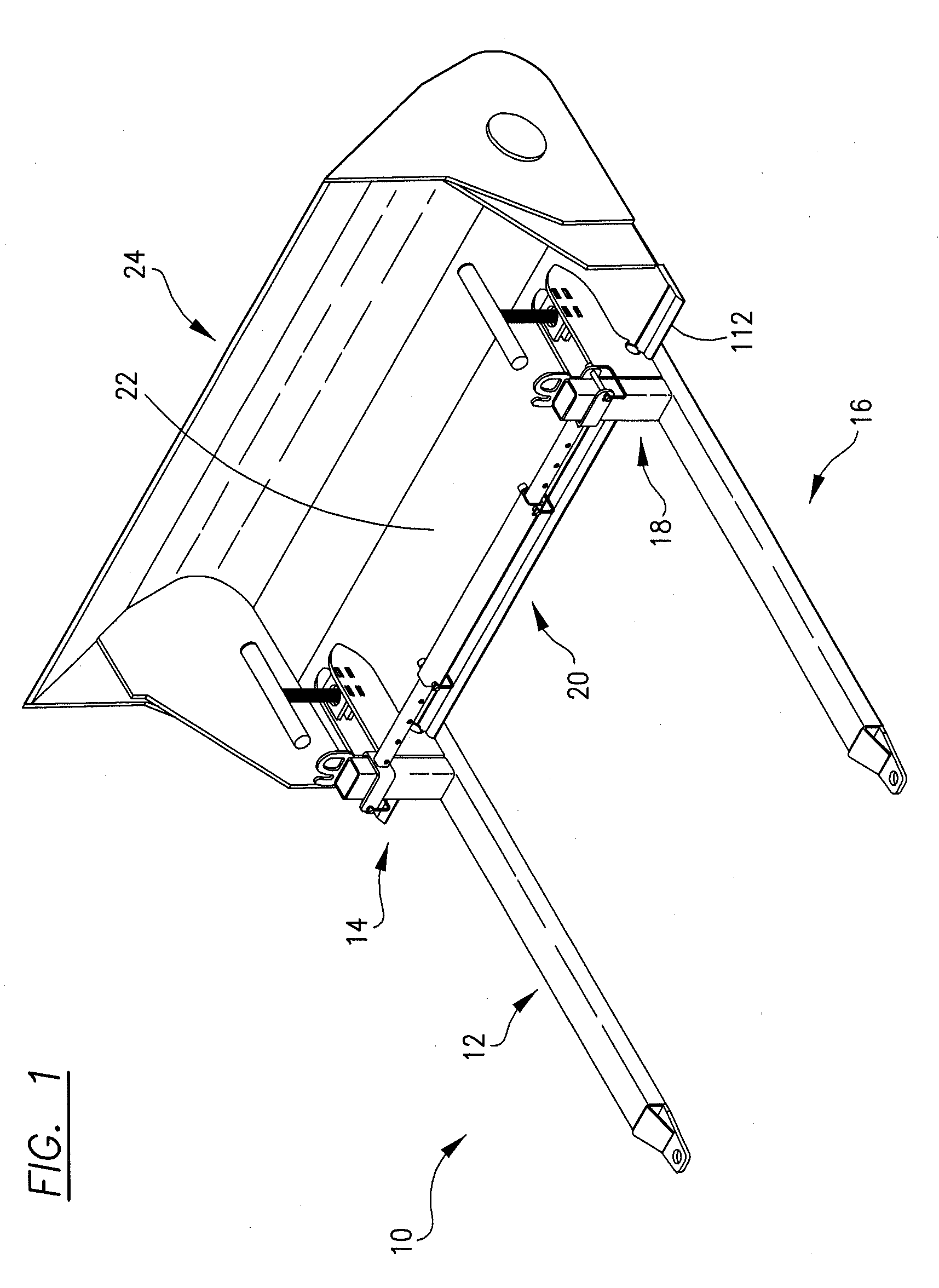
[0014]Referring now to the drawings, the clamp-on fork lift attachment 10 of this invention comprises a first tine 12 having a first clamping mechanism 14, a second tine 16 having a second clamping mechanism 18 and a stabilizer bar 20 which may be connected between the first and second clamping mechanisms 14, 18 of tines 12, 16. The attachment 10 may be mounted to the blade portion 22 of a loader bucket 24, illustrated schematically in FIG. 1, as described in detail below. The loader bucket 24 may be part of a backhoe loader, a front end loader or similar piece of equipment, not shown. For purposes of the present discussion, the terms “top,”“bottom,”“upper,”“lower” and “vertical” refer to the orientation of the various components of the attachment 10 and the loader bucket 24 as depicted in the drawings.

[0015]As best seen in FIG. 1, the two tines 12, 16 and two clamping mechanisms 14, 16 have the same construction. Therefore, only the tine 12 and clamping mechanism 14 are described i...


PUM


Abstract

A clamp-on fork lift attachment having spaced tines which may be temporarily secured to the blade portion of a loader bucket used on equipment such as backhoe loaders and front end loaders includes a lifting plate, a leveling indicator, tie-down elements and a stabilizer bar connected between the spaced tines.

Description

FIELD OF THE INVENTION[0001]This invention relates to devices for use with equipment having a loader bucket, and, more particularly, to a clamp-on fork lift attachment which may be secured to the blade portion of the loader bucket allowing the equipment to function as a fork lift.BACKGROUND OF THE INVENTION[0002]Fork lifts are commonplace in industry and widely used for moving objects resting on pallets and for other purposes. Equipment of this type generally includes a motorized truck having a vertically oriented carriage along which two spaced forks or tines are moveable in and up and down direction. The tines may also be moved toward and away from the truck to assist with the manipulation of loads placed on the tines.[0003]While dedicated fork lifts of the type described above are effective and useful in a variety of applications, they are not always available on job sites and many do not have the size or lifting capacity to handle larger loads. One solution to this problem has b...

Claims


Application Information

Patent Timeline
Patent Type & Authority Patents(United States)
IPC IPC(8): E02F3/96B66F9/14B66F9/12E02F9/26
CPCB66F9/12E02F9/26E02F3/962
Inventor WILLIAMS, DAVID A.FLOYD, AARON
Owner WERNER CO
Learn More