Method for creating a mosaic image using masks

a mosaic image and mask technology, applied in image data processing, character and pattern recognition, instruments, etc., can solve the problems of inaccurate geo-positioning data, aerial images that are not taken exactly perpendicular to the surface of the earth, and inaccuracy of such images up to a dozen meters, so as to achieve greater precision and efficiency.

Active Publication Date: 2016-01-05
TOMTOM GLOBAL CONTENT
View PDF13 Cites 4 Cited by
  • Summary
  • Abstract
  • Description
  • Claims
  • Application Information

AI Technical Summary

Benefits of technology

[0013]According to this invention, a method is provided for creating a mosaic of a large surface of interest such as the Earth from a plurality of small overlapping photographic images. The method comprises the steps of providing a first tile from a first orthorectified photograph of the surface of interest. The first photograph having been taken with a camera at a first distance. The first tile is divided into discrete sections and associated with an absolute coordinate location and orientation relative to the surface of interest. A first mask is provided for the first tile in which any known moving foreground objects are assigned a high priority grayscale value and all other areas in the first tile are assigned a low priority grayscale value. The first mask is divided into discrete sections corresponding to the sections of the first tile. A second tile is provided from a second orthorectified photograph of the surface of interest that at least partly overlaps the first tile. The second photograph having been taking with a camera at a second distance. The second tile is divided into discrete sections and associated with an absolute coordinate location and orientation relative to the surface of interest. A second mask is created for the second tile in which any known moving foreground objects are assigned high priority grayscale values and all other areas in the second tile are assigned a low priority grayscale value. The second mask is divided into discrete sections corresponding to the sections of the second tile. Coincident sections in the first and second tiles, i.e., sections that are associated with the same absolute coordinate location relative to the surface of interest, are compared. The invention is characterized by replacing the coincident section in the first tile with the coincident section from the second tile if the grayscale value of the corresponding section in the second mask has a higher priority than the grayscale value in the corresponding section of the first mask. In other words, moving foreground objects, which are undesirable in a mosaic, are removed by marking the parts in the orthorectified images by use of the supplemental masks. The supplemental masks allow priorities to be established between two or more tiles, which enable the image with the highest priority to be used in the mosaic, where images having lower priority values are discarded. Accordingly, a mosaic of a large surface of interest, such as the Earth, can be generated with greater precision and efficiency than available using prior art techniques.

Problems solved by technology

However, errors are often introduced, which can result in inaccurate mapping of the geo-positioned data.
One problem is that normally aerial images are not taken exactly perpendicular to the surface of the Earth.
The lack of accurate height information of objects in an aerial image, in combination with the triangulation process used to determine the orthorectified image, can result in an inaccuracy of such images up to a dozen meters or more.
However, there is a limit to the accuracy obtained from this method as compared to its cost.
Vertical information cannot be obtained from a typical look-down aerial or satellite image.
While generally effective, it is often the case that moving objects captured in the photograph images, e.g., motor vehicles that are passing or being passed by the mobile mapping vehicle, appear in an overlaying tile but not an underlaying tile, such that a less desirable tile is overlaid upon a more desirable tile.
The use of laser data, particularly in connection with vertical images, is an expensive, cumbersome and less desirable technique for creating orthorectified horizontal images for use in creating a bird's eye mosaic (BEM).

Method used


Image

  • Method for creating a mosaic image using masks
  • Method for creating a mosaic image using masks
  • Method for creating a mosaic image using masks

Examples


Embodiment Construction

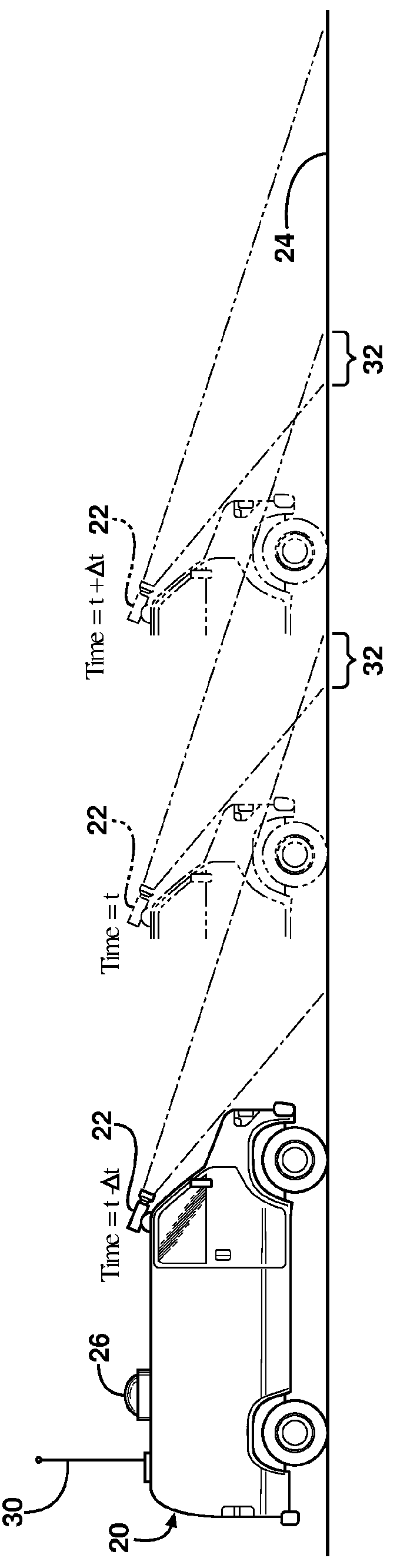
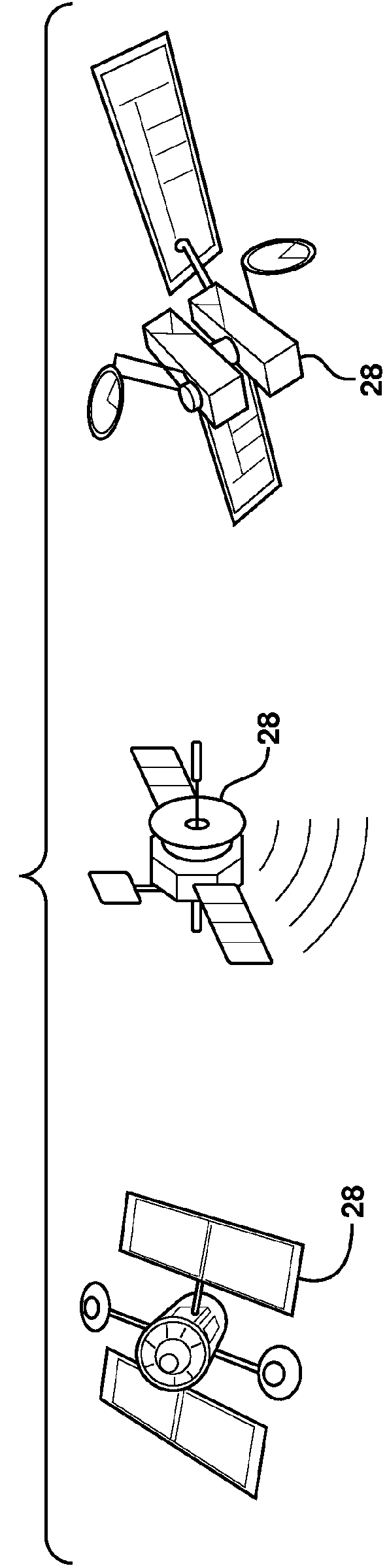
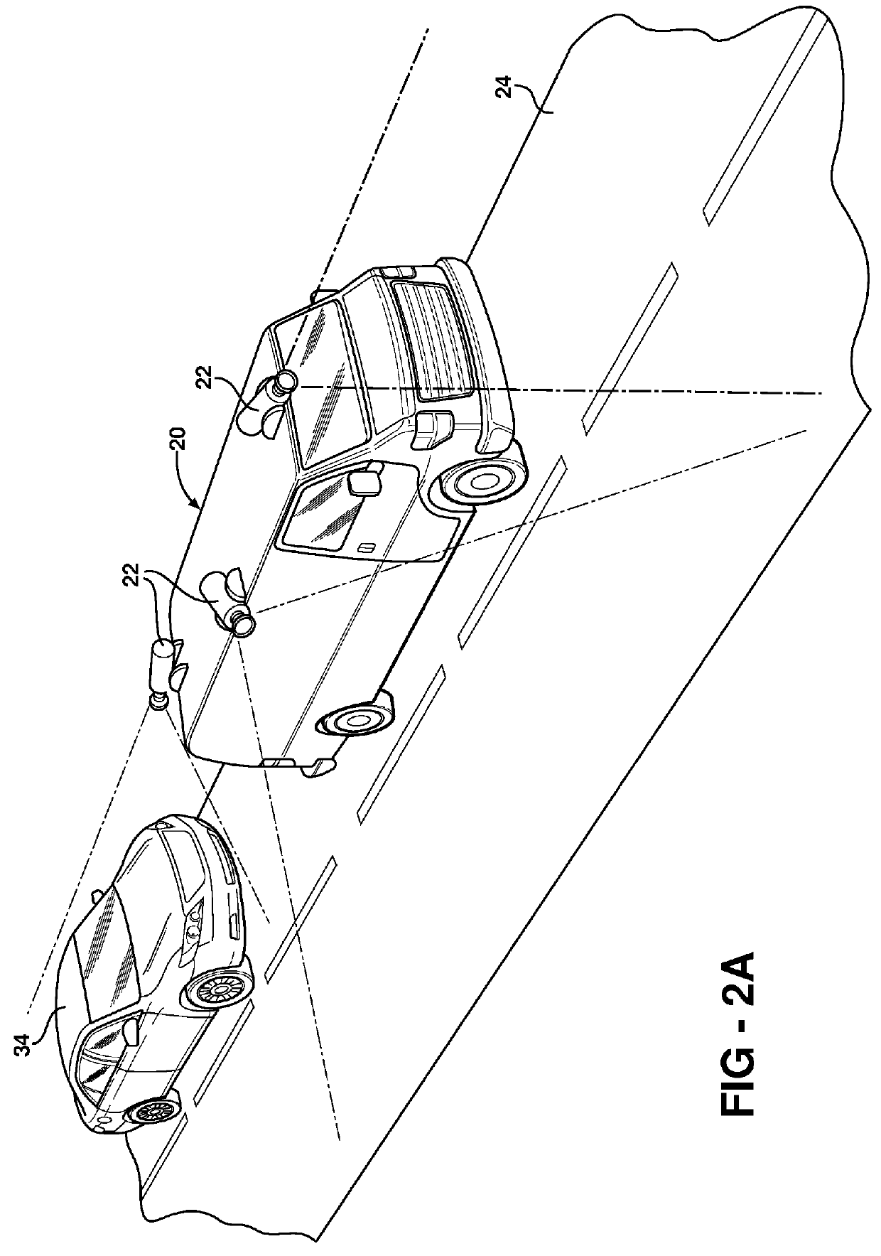
[0038]Referring to the figures, wherein like numerals indicate like or corresponding parts throughout the several views, a mobile mapping vehicle is generally indicated at 20. The mobile mapping vehicle 20 is preferably, but not necessarily, a land based van or automobile fitted with one or more cameras 22 of the type commonly used in geographic mapping applications. The camera 22 is highly calibrated so that pictures taken of a surface of interest 24, such as a roadway, can be geo-coded with a specific location and orientation. This is accomplished, typically, through a GPS receiver 26 which receives positional data from a plurality of satellites 28 orbiting the Earth. Furthermore, orientation determination equipment, e.g., INS, is represented by feature 30 to provide heading data for each image taken by the camera(s) 22. With these devices, each photographic image taken by a camera 22 is geo-coded, meaning that its position, as computed by the GPS receiver 26 and orientation equip...


PUM


Abstract

Photographic images recorded with mobile mapping vehicles (20) in real life situations usually contain cars or other moving objects (34) that cover visual information on the road surface (24). According to the techniques of this invention, moving objects (34) are detected by grayscale differencing in overlapping pixels or sections of two or more orthorectified image tiles. Based on moving object identification, masks are generated for each orthorectified tile. The masks are then compared and priorities established based on grayscale values associated with the masks. Mosaics of a large surface of interest such as the Earth can be assembled from a plurality of overlapping photographic images with moving objects (34) largely removed from the resulting mosaic.

Description

CROSS-REFERENCES TO RELATED APPLICATIONS[0001]This application is the National Stage of International Application No. PCT / EP2009 / 063940, filed Oct. 22, 2009 and designating the United States. The entire content of this application is incorporated herein by reference.BACKGROUND OF THE INVENTION[0002]1. Field of the Invention[0003]The present invention relates to a method for creating a mosaic made up of a plurality of small overlapping photographic images wherein obstructions due to moving foreground objects are minimized.[0004]2. Related Art[0005]Digital maps and digital map databases are used in navigation systems. Digital maps are obtained by various methods, including high resolution imagery from space, as well as orthorectified images taken from land-based mobile vehicles. In the latter case, the images obtained from land-based mapping systems must be converted to an orthorectified image which is scale-corrected and depicts ground features as seen from above in their exact groun...

Claims


Application Information

Patent Timeline
Patent Type & Authority Patents(United States)
IPC IPC(8): G06T3/40
CPCG06T3/4038
Inventor BEKAERT, TIMKACZANOWSKI, PAWELCUPRJAK, MARCIN
Owner TOMTOM GLOBAL CONTENT
Why Eureka
Try Eureka