Circuits and methods for adjusting the voltage swing of a signal

Active Publication Date: 2016-01-05
ALTERA CORP
View PDF13 Cites 16 Cited by
  • Summary
  • Abstract
  • Description
  • Claims
  • Application Information

AI Technical Summary

Benefits of technology

[0004]According to some embodiments, a driver circuit includes unit slice circuits that generate an output data signal based on an input data signal. The driver circuit reduces a voltage swing of the output

Problems solved by technology

When the data signal flips to the opposite logic state after a sequence of bits in the data signal having the same logic state, capacitors in the transmission links may cause the voltage of the data signal to change too slowl

Method used


Image

  • Circuits and methods for adjusting the voltage swing of a signal
  • Circuits and methods for adjusting the voltage swing of a signal
  • Circuits and methods for adjusting the voltage swing of a signal

Examples


Example

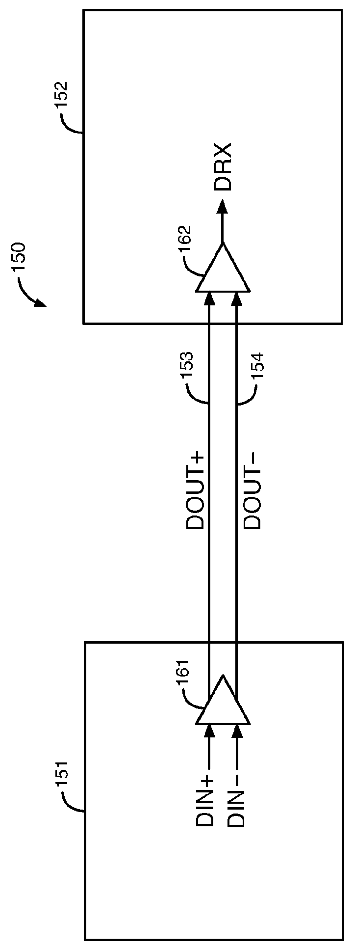
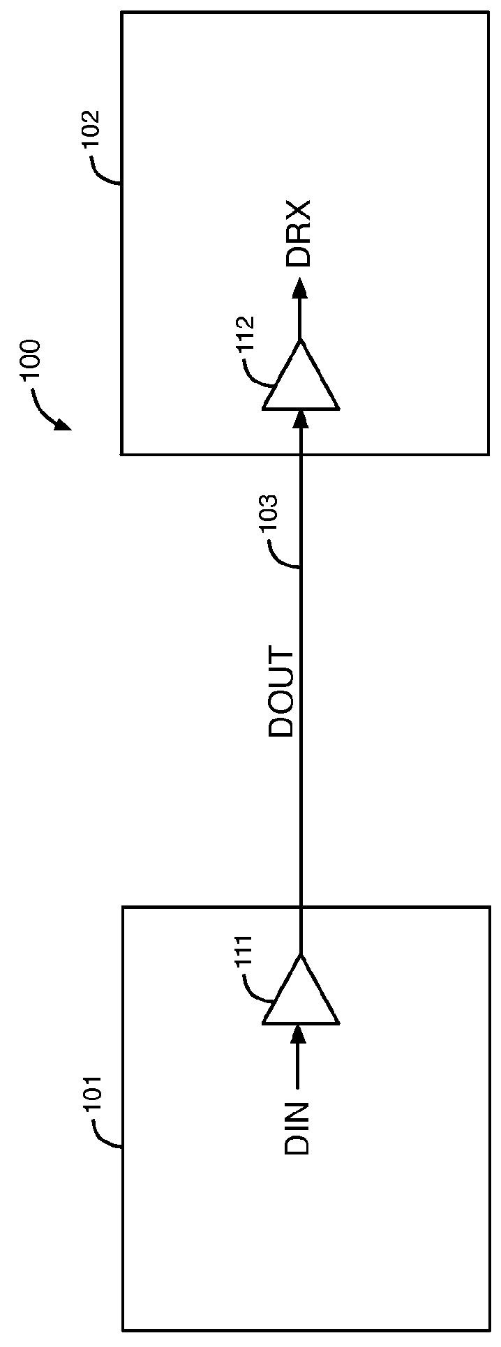
[0019]A current mode driver circuit, such as a current mode logic circuit or an H-bridge circuit, can be used to transmit a data signal in a data transmission system. Alternatively, a voltage mode driver circuit can be used to transmit a data signal in a data transmission system. A voltage mode driver circuit typically consumes substantially less power than a comparable current mode driver circuit. Many high-speed data transmission systems would benefit from lower power consumption in the transmitter.

[0020]Various data transmission protocols may require transmitters to provide different voltage amplitudes in the transmitted data signal. The output current of some voltage mode driver circuits cannot be accurately controlled to generate the different voltage amplitudes in the transmitted data signal that may be required by multiple different data transmission protocols. According to some embodiments disclosed herein, a voltage mode driver circuit can be programmed to vary the voltage ...


PUM


Abstract

A driver circuit includes unit slice circuits that generate an output data signal based on an input data signal. The driver circuit reduces a voltage swing of the output data signal without changing a termination resistance of the driver circuit in response to decreasing a number of the unit slice circuits that generate the output data signal based on the input data signal.

Description

FIELD OF THE DISCLOSURE[0001]The present disclosure relates to electronic circuits, and more particularly to circuits and methods for adjusting the voltage swing of a signal.BACKGROUND[0002]In a data transmission system, one or more data signals are transmitted from a transmitter to a receiver through external transmission links. At a high data rate in the data signal, the unit interval (UI) of each bit in the data signal is very small (e.g., 400 picoseconds at 2.5 gigabit / second). When the data signal flips to the opposite logic state after a sequence of bits in the data signal having the same logic state, capacitors in the transmission links may cause the voltage of the data signal to change too slowly. The effects of the capacitors in the transmission links may cause inter-symbol interference (ISI) in the data signal received by the receiver. ISI may have a negative impact on the performance of the data transmission system.[0003]For example, if the transmitter transmits a sequenc...

Claims


Application Information

Patent Timeline
IPC IPC(8): H04L25/02H03K19/00H04B1/10H03K19/003H03K19/0175
CPCH04B1/1036H04L25/0286H03K19/00361H04L25/0278H03K19/0005H04B2001/1045H04L25/0272H04L25/0288
Inventor KE, YANJINGHOANG, TIM TRI
Owner ALTERA CORP
Why Eureka
Try Eureka