Low voltage differential signaling for communicating with inkjet printhead assembly

Inactive Publication Date: 2002-10-03
HEWLETT PACKARD DEV CO LP
View PDF0 Cites 1 Cited by
  • Summary
  • Abstract
  • Description
  • Claims
  • Application Information

AI Technical Summary

Benefits of technology

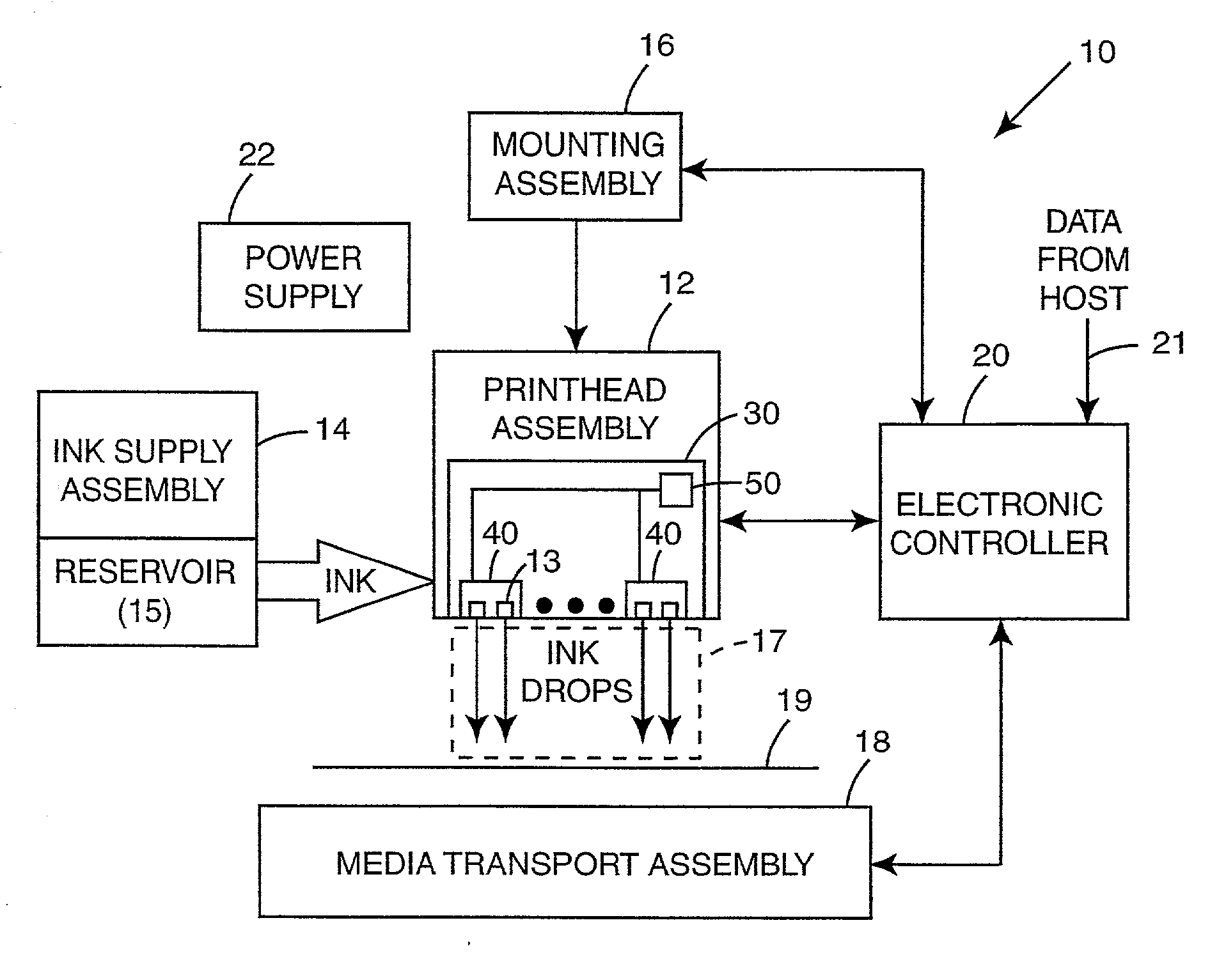
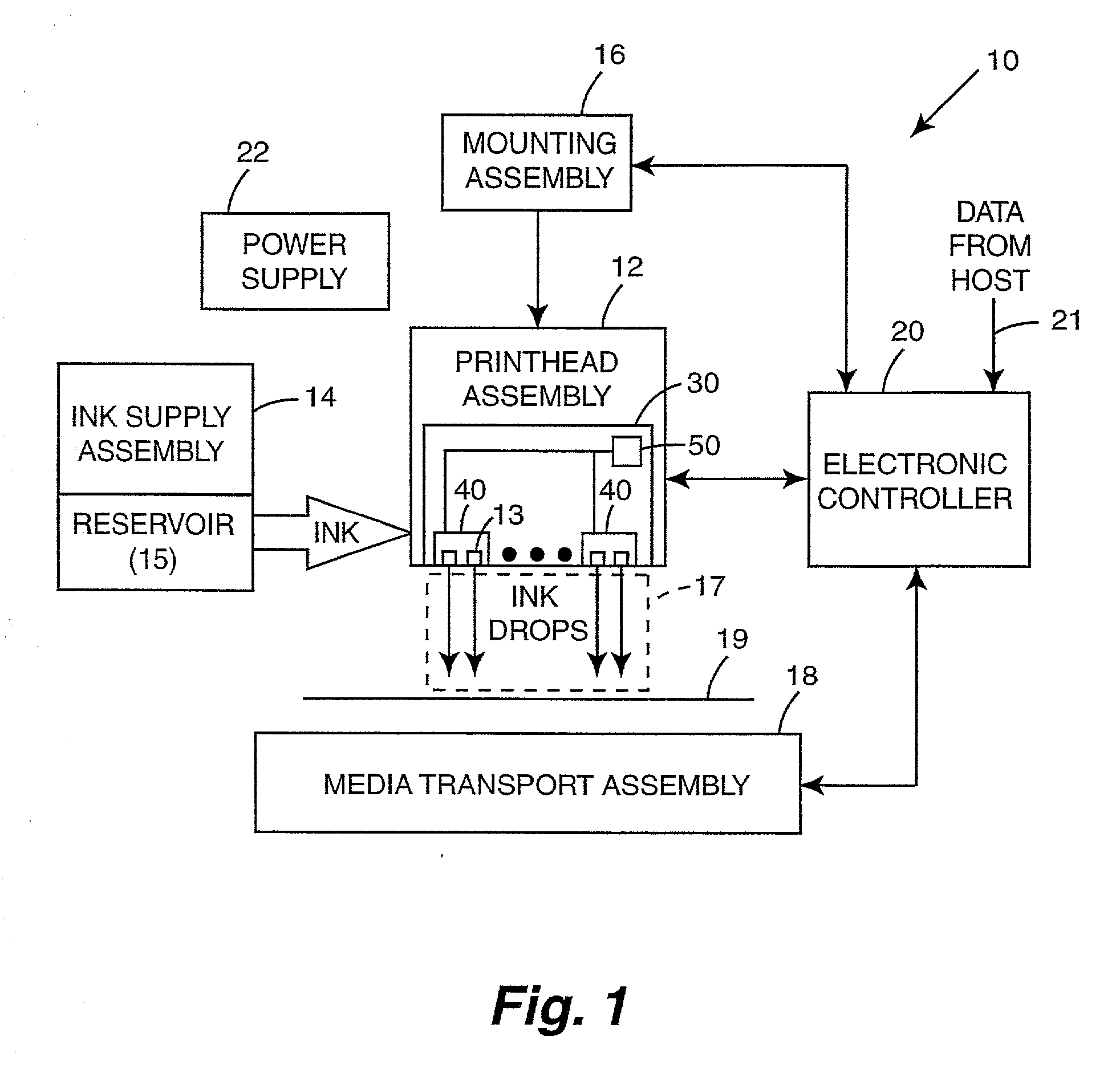
[0017] An inkjet printing system according to the present invention can provide LVDS communication of data and possibly other signals between an electronic controller and a printhead assembly over cabling to substantially reduce voltage swings in the signals carried on the cabling. As a result, the LVDS substantially reduces the amount of EMI conducted and / or radiated by the cabling as compared to the EMI conducted and / or radiated by the cabling in conventional inkjet printing systems, which carries data and other signals between the electronic controller and the printhead assembly using standard CMOS or TTL signaling. Moreover, high-speed signal integrity of the signals carried on the cabling is increased with LVDS, as compared to standard CMOS or TTL signaling.

Problems solved by technology

Voltage switching in the large number of signals carried on the conductive paths generates undesirable electromagnetic interference (EMI).
In addition, the ejection of ink from the nozzles (i.e., firing of the nozzles) requires a switching on and off of a large amount of electrical current in a short amount of time.
The switching on and off of nozzle current of a large number of nozzles simultaneously generates undesirable EMI.
The EMI generated as a result of voltage switching in the signals carried on the conductive paths and nozzle firing causes conductive paths, such as cables, to conduct and / or radiate undesirable EMI.
EMI is undesirable because EMI interferes with internal components of the printing system and can also interfere with other electric devices and appliances not associated with the printing system, such as computers, radios, and televisions.

Method used


Image

  • Low voltage differential signaling for communicating with inkjet printhead assembly
  • Low voltage differential signaling for communicating with inkjet printhead assembly
  • Low voltage differential signaling for communicating with inkjet printhead assembly

Examples


Embodiment Construction

[0026] In the following detailed description of the preferred embodiments, reference is made to the accompanying drawings which form a part hereof, and in which is shown by way of illustration specific embodiments in which the invention may be practiced. In this regard, directional terminology, such as "top," "bottom," "front," "back," "leading," "trailing," etc., is used with reference to the orientation of the Figure(s) being described. The inkjet printhead assembly and related components of the present invention can be positioned in a number of different orientations. As such, the directional terminology is used for purposes of illustration and is in no way limiting. It is to be understood that other embodiments may be utilized and structural or logical changes may be made without departing from the scope of the present invention. The following detailed description, therefore, is not to be taken in a limiting sense, and the scope of the present invention is defined by the appende...


PUM


Abstract

An inkjet printing system includes an electronic controller including electronics providing first signals having first signaling levels, and low voltage differential signaling (LVDS) drivers which receive the first signals and convert the first signals to second signals having LVDS levels. Cabling is coupled to the LVDS drivers and carries the second signals to an inkjet printhead assembly. The inkjet printhead assembly includes LVDS receivers coupled to the cabling and receiving the second signals and converting the second signals to third signals having third signaling levels. One embodiment of the inkjet printhead assembly includes multiple printheads disposed on a carrier to form a wide-array inkjet printhead assembly.

Description

CROSS-REFERENCE TO RELATED APPLICATIONS[0001] This Non-Provisional Patent Application is related to commonly-assigned U.S. Patent Application "MODULE MANAGER FOR WIDE-ARRAY INKJET PRINTHEAD ASSEMBLY" filed on Jan. 5, 2001, with Attorney Docket No. 10002118-1, which is herein incorporated by reference.THE FIELD OF THE INVENTION[0002] The present invention relates generally to inkjet printheads, and more particularly to communicating signals to an inkjet printhead assembly with low voltage differential signaling.BACKGROUND OF THE INVENTION[0003] A conventional inkjet printing system includes a printhead, an ink supply which supplies liquid ink to the printhead, and an electronic controller which controls the printhead. The printhead ejects ink drops through a plurality of orifices or nozzles and toward a print medium, such as a sheet of paper, so as to print onto the print medium. Typically, the orifices are arranged in one or more arrays such that properly sequenced ejection of ink f...

Claims


Application Information

Patent Timeline
IPC IPC(8): B41J2/01B41J2/05B41J29/00
CPCB41J2/04586B41J2/04541
Inventor ANDERSON, DARYL E.SCHLOEMAN, DENNIS J.
Owner HEWLETT PACKARD DEV CO LP
Why Eureka
Try Eureka