Erect posture mobility device with low turn radius

a mobility device and low turn radius technology, applied in the field of mobility devices, can solve the problems of not being designed, deviations in the horizontal platform position, and not being subject to design

Inactive Publication Date: 2016-03-22
POWELL RICHARD RANDAL +1
View PDF33 Cites 27 Cited by
  • Summary
  • Abstract
  • Description
  • Claims
  • Application Information

AI Technical Summary

Benefits of technology

[0023]The saddle structure of the device can also include: a platform frame made of two parallel frame pieces of 90° angled metal strips, which are pre-drilled at intervals both on the tops and the sides, such that the top holes on the frame pieces align with threaded inserts on the underside receiving plate of the forearm seat and allow for threaded bolts to secure the forearm seat in one or more positions to accommodate differing forearm lengths of users; a saddle plane positioning disk with top holes that align with the side holes on the frame pieces; saddle posts with top holes that align with pre-drilled holes of angled grip handle stem and with top holes of the saddle plane positioning disk and the side holes on the frame pieces, such that securing bolts that pass through aligned holes can secure the saddle post, the saddle plane positioning disk, and the grip handle stem between the upright sides of each pair of the platform frame strips for each saddle structure.
[0028]The method includes the placement of forearm of the user on the arm saddle structures such that the forearm is parallel to the ground and the user's center of gravity falls within an area of a base of support of the device that is defined by the contact points of the wheels with the floor, thereby maintaining stable and erect body posture and providing low-radius (e.g., 10 to 15 inches) rotational mobility while the user is engaged in motion. Preferable low-radius rotational mobility has a radius of 12 inches. The arm saddle structure further includes a forearm seat, a saddle plane-positioning disk, a grip handle, a grip handle stem, and a saddle post. The position of the forearm seat can be adjustable to shift the user's center of gravity relative to the base of support.

Problems solved by technology

While arm support platforms have been claimed to assist in maintaining a more erect locomotor posture, the under girding architectures of conventional rollators do not provide for a normal and stable distribution of the user's center of body weight within his base of support or centrally within the rollator's structural base of support.
Furthermore, deviations from the horizontal arm platform position (saggital plane: tilting up or down) or deviations from a linear position (horizontal plane: turning platform inward or outward) have not been designed for the purpose of intentionally changing the position of the user's center of gravity relative to that of the rollator's base of support.
Moreover, deviations in the horizontal platform position have not been a subject of design in accommodating user needs related to stability, walking speed, and body ponderosity.

Method used


Image

  • Erect posture mobility device with low turn radius
  • Erect posture mobility device with low turn radius
  • Erect posture mobility device with low turn radius

Examples


Embodiment Construction

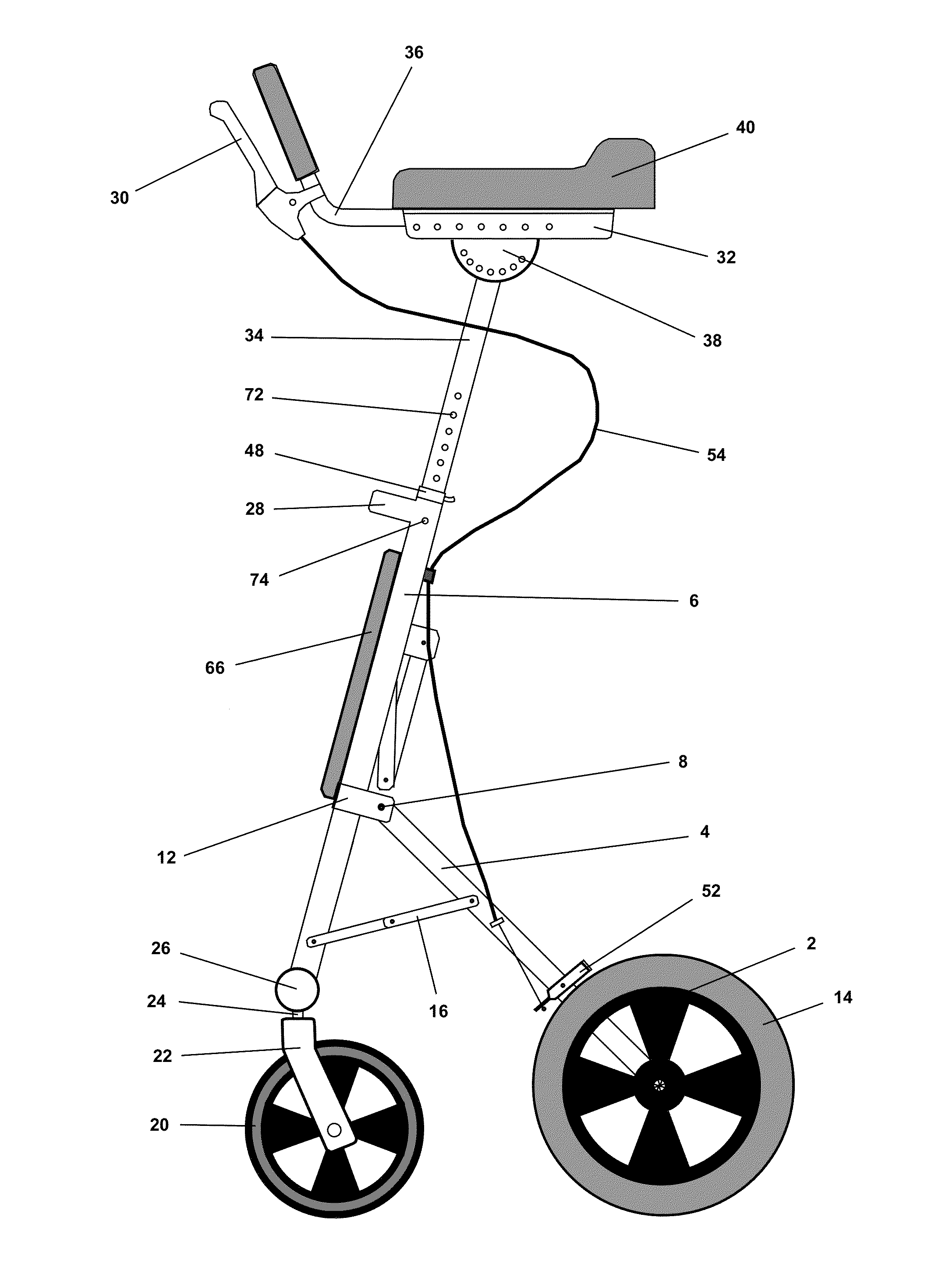
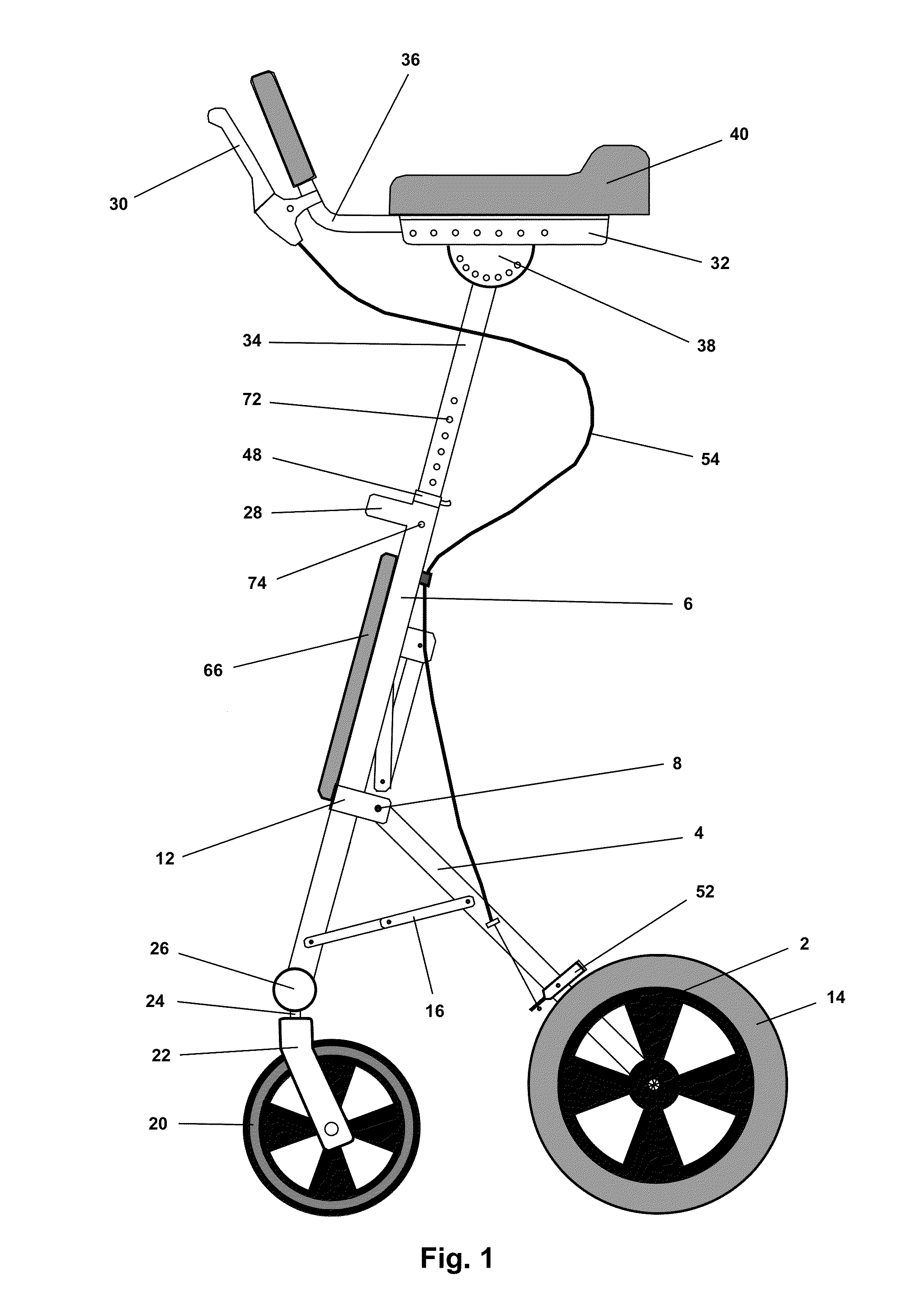
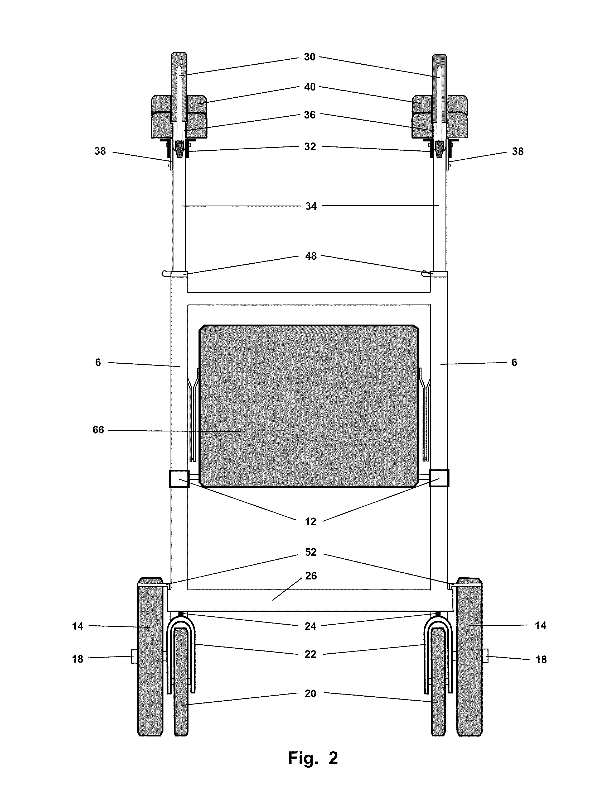
[0039]The present invention describes a mobility device designed to maintain stable and erect body posture of a user and provide low-radius rotational mobility while a user is engaged in motion. The device has a smaller area of base of support, as compared to most conventional rollators.

[0040]In general the device includes the following components: a frame comprising two upright supports; one or more members connecting the two upright supports; two rear wheel struts whose lengths are adjustable; one or more front wheels and two rear wheels; and two arm saddle structures functionally attached to the two upright supports, such that the saddle structures are designed to place the forearm of the user in a position parallel to the ground and such that the user's center of gravity falls within an area of a base of support of the device, thereby maintaining stable and erect body posture and providing low-radius rotational mobility while the user is engaged in motion.

[0041]In general, the u...


PUM


Abstract

The present invention is a mobility device, (also referred to as a “rollator”), which provides a weight bearing architecture and enables the user to maintain an erect body posture and body weight support through the upper arms while enabling the legs to freely move under the user's center of body weight. Upper arm support is enabled through padded forearm rests, or “arm saddles”, which provide an elevated cushion rearward to support and position the user's elbows and transfer the center of the body weight vertically downward and through the rollator frame and thereby falling within its base of support as defined by its four support wheels. The invention's base of support is smaller than conventional rollators, thereby enabling responsive rotational movement by transferring the user's spinal rotation through the aforementioned arm saddles to the rollator frame resulting in a low-radius turn.

Description

TECHNICAL FIELD[0001]The invention relates to a mobility device and related methods. More specifically, the invention relates to an assisted mobility device for maintaining stable and erect body posture of a user and providing low-radius rotational mobility while a user is engaged in motion.BACKGROUND OF THE INVENTION[0002]A wide variety of mobility devices (hereinafter also referred to as “rollators”) exist to assist in bipedal movement. Most of these devices rely upon upper body support being maintained through an extended arm position with hands gripping support bars, which are part of the rollator structure. Several rollator inventions have claimed improvement over conventional rollators by incorporating arm rests rather than grip bars for assistive body support (e.g., as described in US 2005 / 0156395A1, EP 1020173A2, EP 2086493B1, U.S. Pat. Nos. 7,547,027B2 and 7,111,856B1, each of which is herein incorporated by reference).[0003]While arm support platforms have been claimed to ...

Claims


Application Information

Patent Timeline
Patent Type & Authority Patents(United States)
IPC IPC(8): B62B9/12A61H3/04B62B5/00B62B9/00A61H3/00
CPCA61H3/04B62B5/00B62B9/00A61H2003/006A61H2003/046B62B5/0438B62B5/0485B62B5/085B62B9/085B62B2005/0471A61H2201/1623A61H2201/1635A61H2201/0161A61H2201/0192A61H2201/1633
Inventor POWELL, RICHARD RANDALPOWELL, JOHNNA DAWN
Owner POWELL RICHARD RANDAL
Why Eureka
Try Eureka