Flexible expansion joint seal

a flexible expansion joint technology, applied in the field of joint sealing systems, can solve the problems of increasing the chances of sealing failure, and achieve the effect of facilitating interlaying the expansion joint seal

Active Publication Date: 2016-04-26
EMSEAL JOINT SYST
View PDF24 Cites 68 Cited by
  • Summary
  • Abstract
  • Description
  • Claims
  • Application Information

AI Technical Summary

Benefits of technology

[0007]In one embodiment, at least one of the first flange portion and the second flange portion is comprised of a flexible materials such that the at least one of the first flange portion and the second flange portion may be affixed to the structure at an angle or an elevation that differs from the central portion. In one embodiment, at least one of the first flange portion and the second flange portion is bifurcated into an upper flange portion and a lower flange portion. The upper flange portion extends further in length from the centerline than the lower flange portion to facilitate interlaying the expansion joint seal with roofing materials to form a water tight seal of the structure.

Problems solved by technology

For example, the fasteners 16 and 26 are exposed to weather conditions and the seals may fail as they deteriorate and no longer effectively anchor the seals 10 and 20 about the joint J. Additionally, the seals 10 and 20 provide only a single layer of waterproofing, increasing the chances of failure of the seals.

Method used


Image

  • Flexible expansion joint seal
  • Flexible expansion joint seal
  • Flexible expansion joint seal

Examples


Embodiment Construction

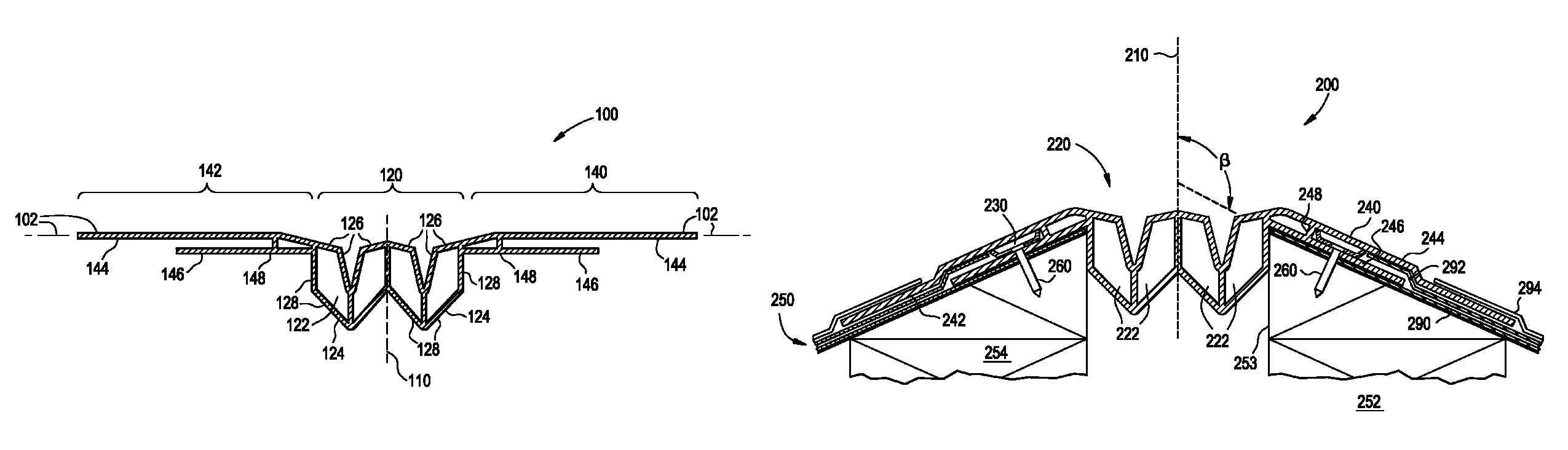
[0018]The present invention alleviates perceived problems associated with current rooftop expansion joint systems by including, for example, redundant levels of waterproofing, a dual flange apparatus, which protects the anchors and enhances the seal, and the ability to manufacture transitions that can be integrated into coplanar, perpendicular and other expansion joints.

[0019]Referring to FIG. 3, an expansion joint seal 100 consists of a central portion 120 disposed around a centerline 110 of the seal 100 and at least one of a first flange portion 140 and a second flange portion 142. A first continuous surface 102 of the joint seal 100 is defined by the center portion 120, the first flange portion 140, and the second flange portion 142. As described in detail below, when installed and affixed on a roof of a structure, the joint seal 100 is integrally incorporated with roofing materials on the roof such that the first surface 102 forms a seal S of a joint or gap G between structural ...


PUM


Abstract

An expansion joint seal for a structure includes a central portion having at least one central chamber disposed around a centerline, a first flange portion extending outwardly from the centerline and a second flange portion extending outwardly from the centerline in a direction opposite the first flange portion. When installed on the structure, the first flange portion is attachable to a first substrate of the structure and the second flange portion is attachable to a second substrate of the structure such that the central portion is disposed within and seals a gap formed between the first substrate and the second substrate of the structure. Movement of one or both of the first substrate and the second substrate causes a response in the central portion to maintain the seal.

Description

CROSS-REFERENCE TO RELATED APPLICATIONS[0001]The present application claims the benefit of U.S. Provisional Patent Application Ser. No. 61 / 547,476, filed Oct. 14, 2011, entitled “THERMOPLASTIC EXPANSION JOINT SEAL FOR ROOFS,” the contents of which is hereby incorporated by reference in its entirety.FIELD OF THE INVENTION[0002]The present invention is generally directed to joint sealing systems, and more particularly, to systems for sealing structural expansion joint openings in roofs of structures.BACKGROUND OF THE INVENTION[0003]In many construction projects involving materials such as concrete and steel, gaps are left between adjacent structural elements to allow for thermal expansion and contraction, wind sway, settlement, live load deflection, and / or seismic movements of the structural elements. By permitting expansion and contraction, the gaps prevent the structural materials and / or building cladding elements from cracking or buckling. These gaps are referred to as expansion jo...

Claims


Application Information

Patent Timeline
Patent Type & Authority Patents(United States)
IPC IPC(8): E04B1/686E04D13/15E04B1/68
CPCE04B1/6813E04D13/151E04B1/681E04D13/1415
Inventor HENSLEY, LESTER
Owner EMSEAL JOINT SYST
Why Eureka
Try Eureka