Check patentability & draft patents in minutes with Patsnap Eureka AI!

Yarn feeder provided with a stationary drum and with a controlled, weft-braking device

a technology of weft braking and feeder, which is applied in the direction of weaving, textiles and papermaking, looms, etc., can solve the problems of high inertia, high cost, and high manufacturing complexity, and achieves fast reaction times, reduced energy consumption, and easy manufacturing.

Active Publication Date: 2016-05-31
L G L ELECTRONICS
View PDF16 Cites 2 Cited by
  • Summary
  • Abstract
  • Description
  • Claims
  • Application Information

AI Technical Summary

Benefits of technology

The piezoelectric weft-braking system is easier to manufacture, operates with lower currents, and achieves faster reaction times compared to electromagnetic systems, reducing energy consumption and maintenance needs.

Problems solved by technology

However, the above-mentioned device has the drawback that it is relatively complex—and therefore expensive—to manufacture both from the mechanical point of view and in relation to the dedicated power electronics required.
Also, the electromagnetic drive is not entirely satisfactory in terms of reaction times, because the excitation times of the coils are notoriously non-negligible and the movable masses involved are considerable, thereby resulting in a high inertia.
In addition, the electromagnetic drive requires high currents and, therefore, high power, with consequent disadvantages in terms of energy consumption, especially in view of the fact that a conventional textile / knitting line often makes use of dozens of feeders for a single downstream machine.

Method used


Image

  • Yarn feeder provided with a stationary drum and with a controlled, weft-braking device
  • Yarn feeder provided with a stationary drum and with a controlled, weft-braking device
  • Yarn feeder provided with a stationary drum and with a controlled, weft-braking device

Examples


second embodiment

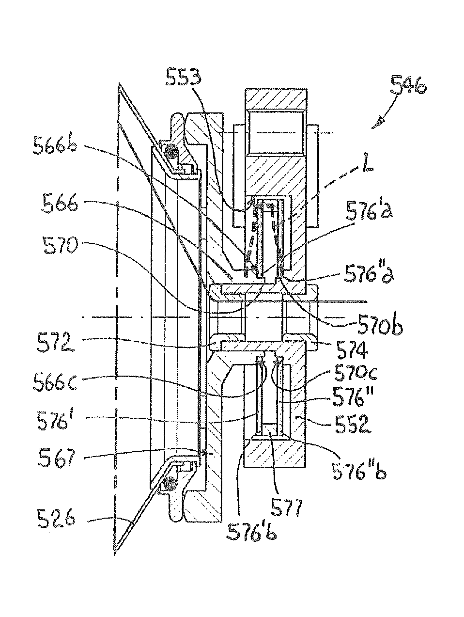
[0059]FIGS. 19-21 show a sixth alternative embodiment of the invention, in which hollow rod 666 is supported by a pair of coaxial, annular elastic diaphragms 681′, 681″, which are received in a through opening 664 formed in a support plate 652 similar to the one shown in FIG. 9. Also in this case, similarly to the embodiment of FIG. 9, two piezoelectric bending actuators 676′, 676″ are provided, which are connected to respective forked arms 680′, 680″ projecting radially from support plate 646 to diametrically opposite positions. Flange 667 is monolithically formed at the end of hollow rod 666 facing the braking member. The opposite end narrows into a neck 666b defining an annular abutment 666c. Diaphragms 681′, 681″ are fitted on neck 666b of hollow rod 666, with interposition of a spacer 677, and are axially sandwiched between annular abutment 666c and a nut 669. The outer edges of diaphragms 681′, 681″ are locked in respective annular seats 683′, 683″ which are formed at the oppo...

first embodiment

[0061]A few preferred embodiments of the invention have been described herein, but of course many changes may be made by a person skilled in the art within the scope of the claims. In particular, although piezoelectric bending actuators having a monolithic, multilayer structure are preferable, bimorph actuators (i.e., actuators having only two layers) could be sufficient for certain applications. Moreover, with all the above-described embodiments the movable, operative end of the piezoelectric actuator directly acts on the hollow rod (or on a body integral to the hollow rod) in a substantial longitudinal direction; however, depending on the circumstances, transmission means, as devised by the person skilled in the art, could be interposed. In addition, it should be understood that, with slight constructional changes, the piezoelectric actuator could have its inner end / edge fixed and push the braking member with its outer end, contrary to what has been described in the above embodime...


PUM


Abstract

A drum has a plurality of yarn loops wound thereon which are to be unwound upon request from a downstream machine. A weft-braking device provided with a braking member having a circular profile is biased against a delivery edge of the drum by driving elements. The yarn is adapted to run between the delivery edge and the braking member to receive a braking action by friction from them. The driving elements comprise at least one piezoelectric actuator which is deformable in response to a voltage applied thereto and has a movable operative end which is operatively connected to the braking member and a stationary operative end which is anchored to a stationary support.

Description

[0001]The present invention relates to a yarn feeder provided with a stationary drum and with a controlled, weft-braking device.BACKGROUND OF THE INVENTION[0002]As known, a yarn feeder for textile / knitting lines typically comprises a stationary drum on which a motorized flywheel winds a plurality of yarn loops forming a well reserve. Upon request from a downstream machine, e.g., a loom, the loops are unwound from the drum and, before reaching the machine, the yarn passes through a weft-braking device that influences the tension of the unwinding yarn.[0003]A typical weft-braking device may comprise a hollow, frustoconical braking member, which is biased with its inner surface against the delivery end of the stationary drum in order to pinch the unwinding yarn and brake it by friction.[0004]A weft-braking device of the above-mentioned type can apply a static, adjustable braking action to the yarn or, according to the teachings of EP 1717181 B1 of Applicant, it can be operatively conne...

Claims


Application Information

Patent Timeline
Patent Type & Authority Patents(United States)
IPC IPC(8): B65H51/22D03D47/34D03D47/36
CPCD03D47/364B65H51/22D03D47/347D03D47/366
Inventor BERTOCCHI, GIORGIOPEDRINI, GIOVANNIZENONI, PIETRO
Owner L G L ELECTRONICS
Features
  • R&D
  • Intellectual Property
  • Life Sciences
  • Materials
  • Tech Scout
  • Unparalleled Data Quality
  • Higher Quality Content
  • 60% Fewer Hallucinations
Learn More