Wire feeding systems and devices

a wire feeding system and wire technology, applied in the direction of electrode supporting devices, manufacturing tools, transportation and packaging, etc., can solve the problems of interrupting welding operation, operator may not know the quantity of wire remaining on the spool, fed wire consumed in welding operation,

a wire feeding system and wire technology, applied in the direction of electrode supporting devices, manufacturing tools, transportation and packaging, etc., can solve the problems of interrupting welding operation, operator may not know the quantity of wire remaining on the spool, fed wire consumed in welding operation,

US9403234B2Active Publication Date: 2016-08-02ILLINOIS TOOL WORKS INC

Image

  • Wire feeding systems and devices
  • Wire feeding systems and devices
  • Wire feeding systems and devices

Examples


Embodiment Construction

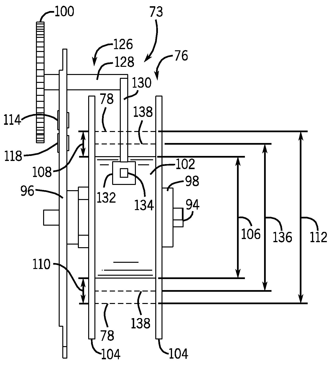
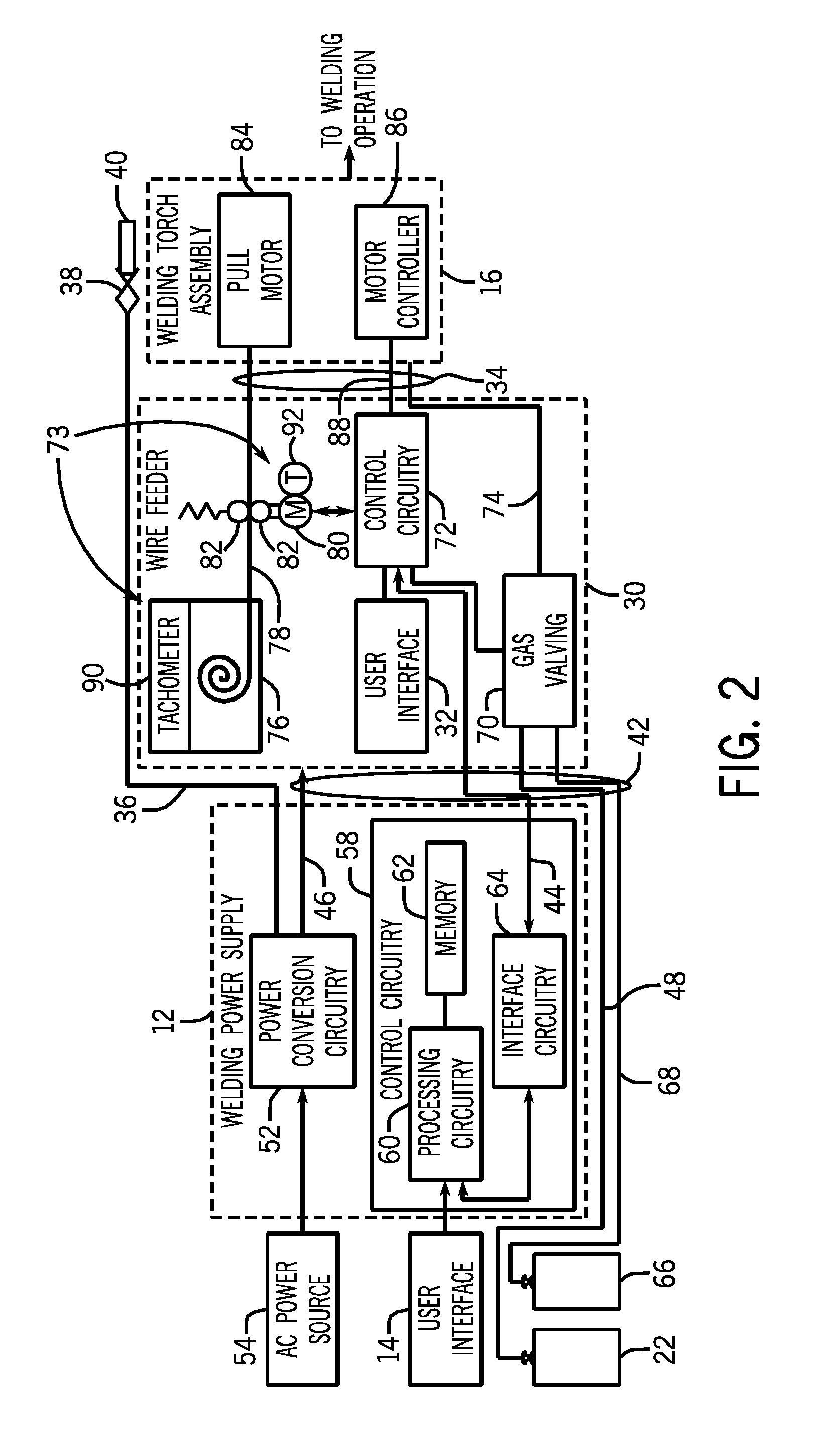
[0023]As described in detail below, provided herein are embodiments of welding wire feed systems capable of directly or indirectly monitoring an outer diameter of a wire spool. For example, in certain embodiments, a sensing system may include a speed / position sensor (e.g., a tachometer) coupled to a wire spool and / or a wire spool hub on which the wire spool is mounted. In these embodiments, the tachometer measures the rotational speed of the wire spool as wire is unwound from a core of the wire spool. Control and processing circuitry may utilize the measured rotational speed of the wire spool to determine an outer diameter of the wire spool at any given point during a welding operation. Further, the control circuitry may utilize the outer diameter to control and / or monitor the welding process, for example, by tracking the outer diameter of the wire spool over time, utilizing the determined outer diameter to control an operational parameter of the welding process, utilizing the outer...


PUM

PropertyMeasurementUnit
core diameteraaaaaaaaaa
outer diameteraaaaaaaaaa
rotational speedaaaaaaaaaa

Abstract

Provided herein are systems including a wire spool having a core with a core diameter and wire wound around the core and having a wire diameter. An outer diameter of the wire spool is defined by a sum of the core diameter and the wire diameter. The systems may also include a sensing system having a sensor component disposed on the wire spool and / or a wire spool hub. The sensing system is adapted to acquire data corresponding to a parameter indicative of the outer diameter of the wire spool.

Description

CROSS REFERENCE TO RELATED APPLICATIONS[0001]This application is a Non-provisional patent application of U.S. Provisional Patent Application No. 61 / 556,641, entitled “Wire Feeding Systems and Devices”, filed Nov. 7, 2011, which is herein incorporated by reference.BACKGROUND[0002]The invention relates generally to welding wire feed systems, and, more particularly, to sensing systems for monitoring a wire spool size during a welding operation.[0003]Welding is a process that has become ubiquitous in various industries for a variety of types of applications. For example, welding is often performed in applications such as shipbuilding, aircraft repair, construction, and so forth. Such welding operations rely on a variety of types of equipment to ensure the supply of welding consumables (e.g., wire feed, shielding gas, etc.) is provided to the weld in an appropriate amount at the desired time. For example, metal inert gas (MIG) welding typically relies on a wire feeder to ensure a proper ...

Claims


Application Information

Patent Timeline
02 Aug 2016
Publication
US9403234B2
IPC
B23K9/12; B65H63/08; B65H59/38; B23K9/133
CPC
B23K9/1333; B65H63/082; B65H59/387; B65H2701/36
Inventors
CHRISTOPHER, MARK R.; OTT, BRIAN LEE