
Valve assembly for a central tire inflation system

a technology of valve assembly and central tire inflation, which is applied in the direction of mechanical equipment, transportation and packaging, valve types, etc., can solve the problems of system backpressure increase, and achieve the effect of reducing the diameter

Active Publication Date: 2016-08-16
DANA HEAVY VEHICLE SYSTEMS GROUP LLC
View PDF80 Cites 8 Cited by
  • Summary
  • Abstract
  • Description
  • Claims
  • Application Information

AI Technical Summary

Problems solved by technology

As the flow through the tire inflation system increases, backpressure in the system increases.

Method used


Image

  • Valve assembly for a central tire inflation system
  • Valve assembly for a central tire inflation system
  • Valve assembly for a central tire inflation system

Examples


Embodiment Construction

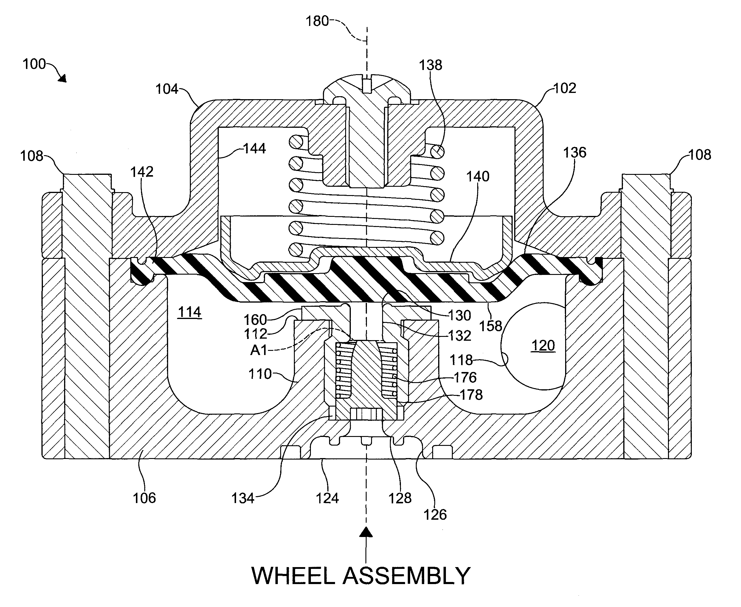
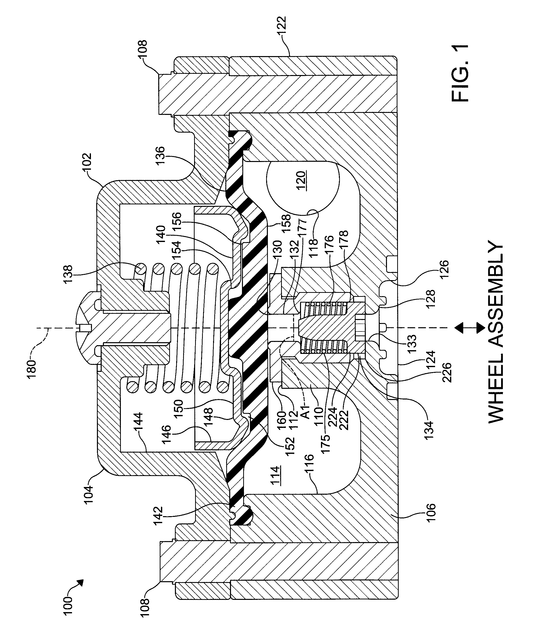
[0030]It is to be understood that the invention may assume various alternative orientations and step sequences, except where expressly specified to the contrary. It is also to be understood that the specific assemblies and features illustrated in the attached drawings, and described in the following specification are simply exemplary embodiments of the inventive concepts. Hence, specific dimensions, directions, or other physical characteristics relating to the embodiments disclosed are not to be considered as limiting, unless expressly stated otherwise. Also, although they may not be, like elements in various embodiments may be commonly referred to with like reference numerals within this section of the application.

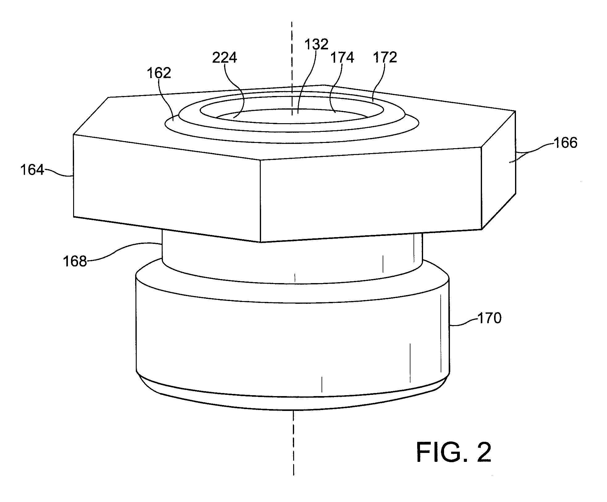
[0031]Embodiments of a valve assembly 100, 300, 500 are described herein. It would be understood by one of ordinary skill in the art that the valve assembly 100, 300, 500 may have applications to passenger, commercial and off-highway vehicles. Also, it would be understood...


PUM


Abstract

A valve assembly for a central tire inflation system is provided. The valve assembly includes a first housing having a first port connected to a second port via a cavity. The second port is in fluid communication with a wheel assembly. A biasing member is disposed in the cavity adjacent a first perforation formed in the first housing. A valve member is contacted by the biasing member. The valve member includes a first portion having an outer surface which is unbroken adjacent an end to allow a pressurized fluid to flow around it. The first portion reduces in diameter toward the end.

Description

CROSS-REFERENCE TO RELATED APPLICATIONS[0001]This application is claiming the benefit, under 35 U.S.C. 119(e), of the provisional applications granted Ser. Nos. 61 / 763,048 filed on Feb. 11, 2013, 61 / 776,431 filed on Mar. 11, 2013, 61 / 792,778 filed on Mar. 15, 2013, 61 / 865,790 filed on Aug. 14, 2013 and 61 / 925,749 filed on Jan. 10, 2014 the entire disclosures of which are hereby incorporated by reference.BACKGROUND OF THE INVENTION[0002]The invention relates to a valve assembly. More specifically, the invention relates to a valve assembly for a central tire inflation system.[0003]Current valve designs used in tire inflation systems have minimum and maximum pressure limits which are a function of the operational temperature requirements and the backpressure characteristics of the system. As the flow through the tire inflation system increases, backpressure in the system increases. At higher flow rates and backpressures, the pressure experienced by current valve designs can be such tha...

Claims


Application Information

Patent Timeline
Patent Type & Authority Patents(United States)
IPC IPC(8): F16K15/20B60C23/00B60C29/00
CPCB60C23/003B60C29/002Y10T137/3584Y10T137/88062Y10T137/3631B60C23/00318B60C23/00354B60C23/00363F16K15/20
Inventor RACINE, LLOYD G.SIDDERS, JASON M.LEE, PHENGBALISTRERI, LUCAS A.
Owner DANA HEAVY VEHICLE SYSTEMS GROUP LLC
Learn More