
Method for monitoring physical parameters of well equipment
a technology for physical parameters and well equipment, applied in the direction of optical detection, survey, borehole/well accessories, etc., can solve the problems of significant risk of cable breakage, cumbersome and time-consuming installation of sensing cables,
- Summary
- Abstract
- Description
- Claims
- Application Information
AI Technical Summary
Benefits of technology
Problems solved by technology
Method used
Image

Examples
Embodiment Construction
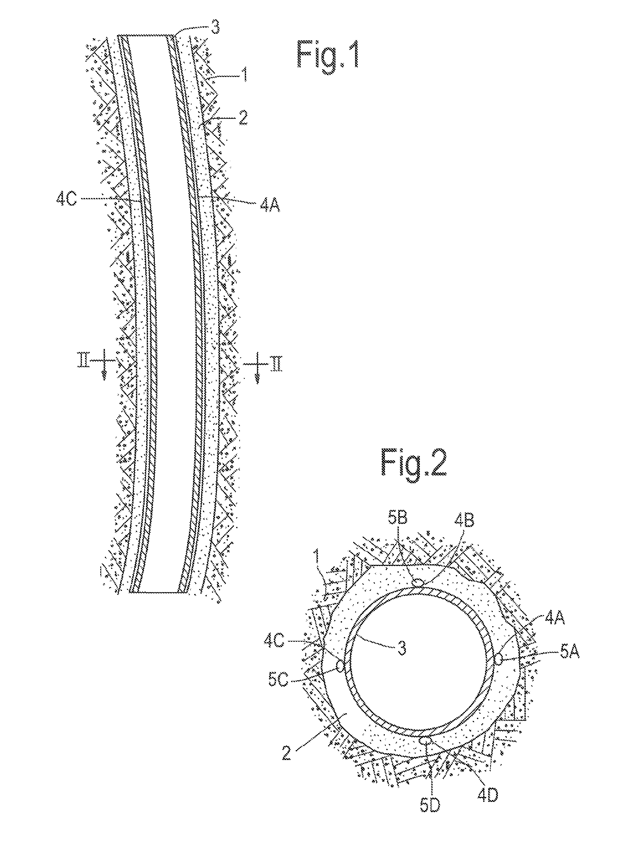
[0023]FIG. 1 shows a curved wellbore 1 in which a bend casing 2 is arranged. The casing 2 is secured within the wellbore 1 by cement 3, which fills the annular space between the outer surface of the casing 2 and the inner surface of the wellbore 1.
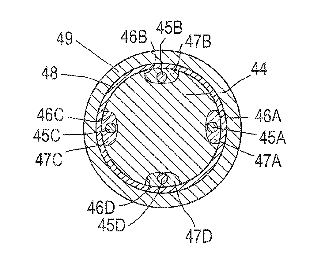
[0024]In order to monitor stress, deformation, temperature and other features a series of four rods 4A-4D are embedded in the cement 3 around the casing 2. As illustrated in FIG. 2 each rod has a recess in which an optical strain monitoring fiber 5A-5D is embedded. The rods 4A-4D are preferably made of the same metal as the casing 2.
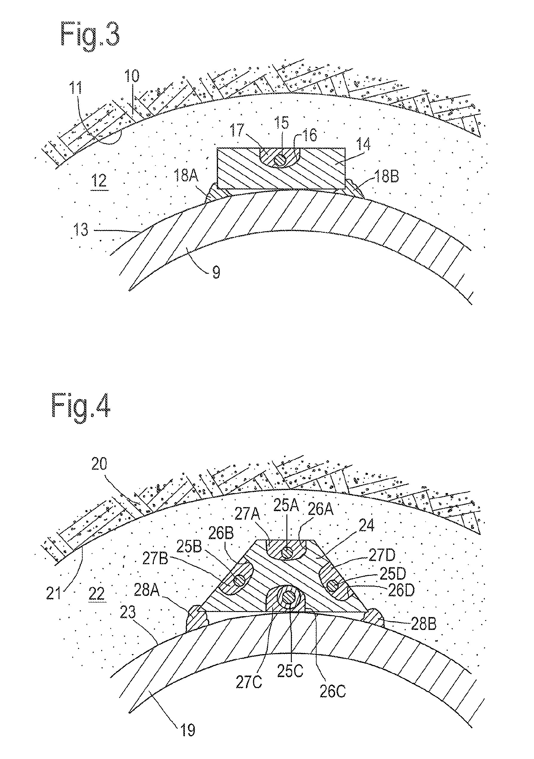
[0025]FIG. 3 shows in more detail a cross sectional view of an alternative embodiment of a rod 14, wherein the rod has a rectangular shape and is arranged in a cement body 12 between the inner surface 11 of a wellbore in an underground earth formation 10 and the outer surface 13 of a casing 9. The rod 14 has a recess 16 in which an optical strain monitoring fiber 15 is embedded within a protective filler 17. Th...
PUM
 Abstract
Description
Claims
Application Information