
Safety gas valve capable to attain a blocking condition when subjected to a flow in excess of its nominal working conditions

a safety gas valve and flow condition technology, applied in the field of safety valves, can solve problems such as fire, explosion, fire, etc., and damage to property and persons, and achieve the effect of blocking conditions when subjected to flow in excess of the nominal working conditions

Active Publication Date: 2016-11-15
MUSTAFA JORGE ISMAEL
View PDF1 Cites 2 Cited by
  • Summary
  • Abstract
  • Description
  • Claims
  • Application Information

AI Technical Summary

Benefits of technology

[0010]The main object of this instant invention is to provide a safety valve which, when placed between a gas source and the device to which said gas is being fed, such as a gas flow regulator, it allows to block the exit of said gas from said source when faced with a flow of gas in excess of the nominal values allowed by the device making use of said fluid, being this excess flow provoked by either damage to the device, or by rupture or severance of the feeding conduits, or including, by malfunctioning of said gas flow regulator, while, at the same, within this same safety device construction it is provided the means to reset the free passage of gas, thus restoring the working conditions after having suffered said blocking conditions, by performing a simple and single operation clearing the blocking situation acting directly over said blocking means with the safety valve of the invention, without the need of any tools, and without the need to disassemble any part thereof, and most important, without the need to interrupt the fluid supply.
[0012]A further object of this instant invention is that in one of its embodiments this safety valve is calibrated to operate with a gas source at a relatively low pressure, for example 2 to 10 atmospheres, while in another of its constructions, this same device can perform under higher pressure, such as 200 to 300 atmospheres, allowing to reset the working conditions even under such high pressures.

Problems solved by technology

One of the many problems encountered in the course of the use of said regulators counter or prevent the issue of an excess flow of gas, usually at a higher pressure, provoked, among other reasons, either by damage or severance of the tube or conduit connecting the source of gas to the appliance, or by failure of this same device or appliance, including the eventual shattering or damage to said gas regulator's feeds.
In all said cases, the gas will be released at a larger volume and / or pressure, flooding the space (e.g., a room where said appliance is installed) and my cause fires, explosions, etc. with damage to property and persons.
Another drawback of these known regulators is given at the moment a device or appliance is being connected to the source of gas or supply line.
At present, in order to be able to perform safely said connection it is necessary to close the stopcock feeding said gas from said source, thus preventing a sudden release of gas under pressure, and if by any reason said check valve is placed at a far distance, from said connection, to close timely said valve may constitute an inconvenience.
The same can be argued when the supply line is already connected to a gas flow regulator, because if said connection is being performed with said stopcock in an “open” position, the user may face risks.
To date there are no known in the art safety devices placed between the under pressure gas source and the appliance supplied with said gas which allows for an automatic blocking or closure of said gas source when faced with a sudden excess of the nominal gas flow rate; further, it is also unknown to have a device that, upon said blocking, may at the same time provide the means to reset the nominal fluid gas flow conditions without having the dissemble part of the valve, or to close the taps and / or closing the line of conduit of gas delivery, being this resetting performed within the same security valve by means of a simple resetting operation performed without the need of any special tool, in a simple and one step operation,

Method used


Image

  • Safety gas valve capable to attain a blocking condition when subjected to a flow in excess of its nominal working conditions
  • Safety gas valve capable to attain a blocking condition when subjected to a flow in excess of its nominal working conditions
  • Safety gas valve capable to attain a blocking condition when subjected to a flow in excess of its nominal working conditions

Examples


Embodiment Construction

[0015]In order to achieve examples of the preferred embodiments of the present invention, the following drawings which illustrate it are given, in support of the description thereof given hereinafter; these constructions are understood as one of the many possible constructions of this instant invention, therefore it corresponds to give to the embodiments no limiting value of the invention, being included in these constructions and within the scope of protection of this invention all the equivalent means achieving the same results, while the amplitude and scope of the present invention is determined by the first claim herewith attached.

[0016]In all the following figures, the same reference numbers are identifying equal means or their equivalents.

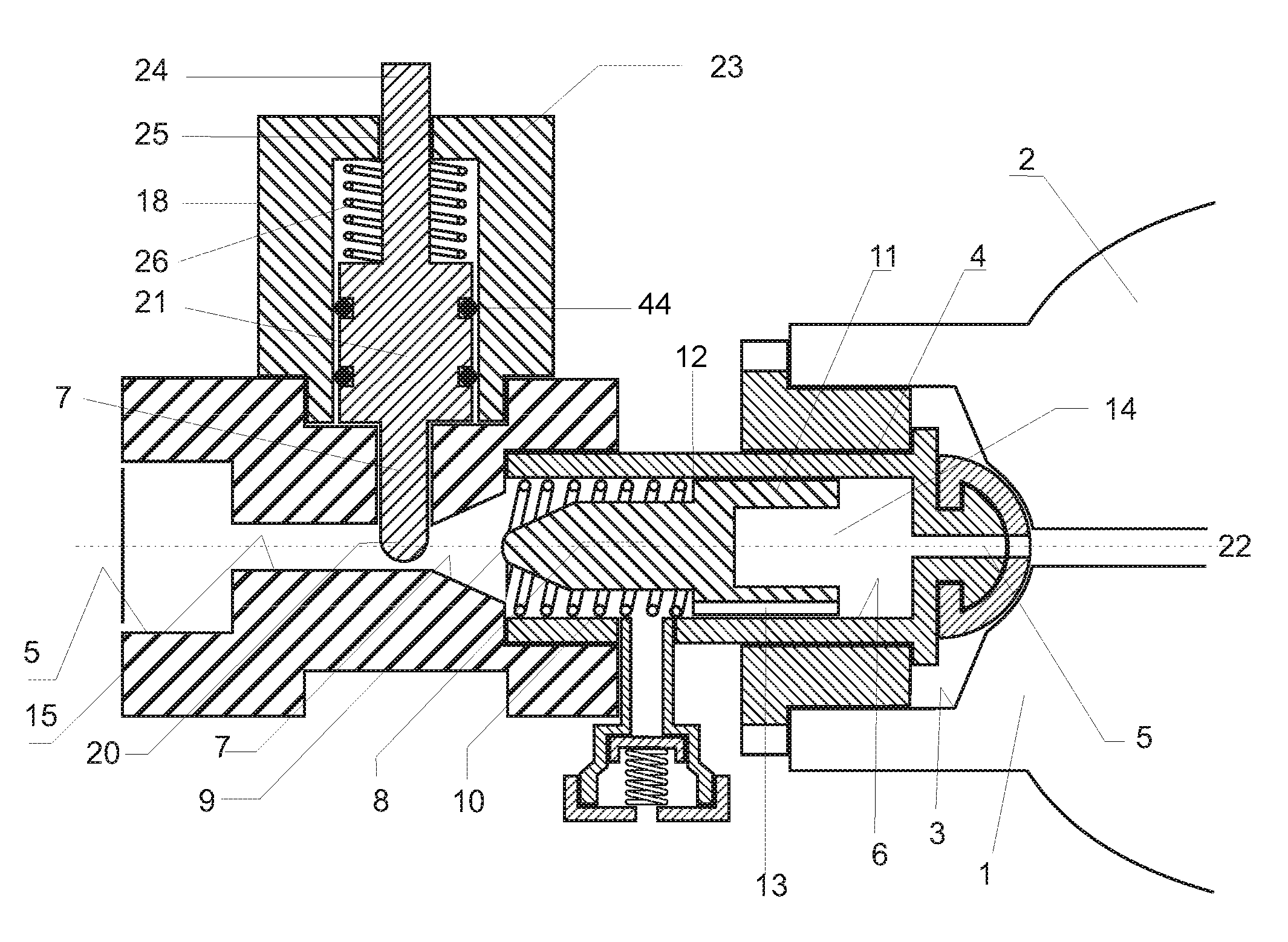
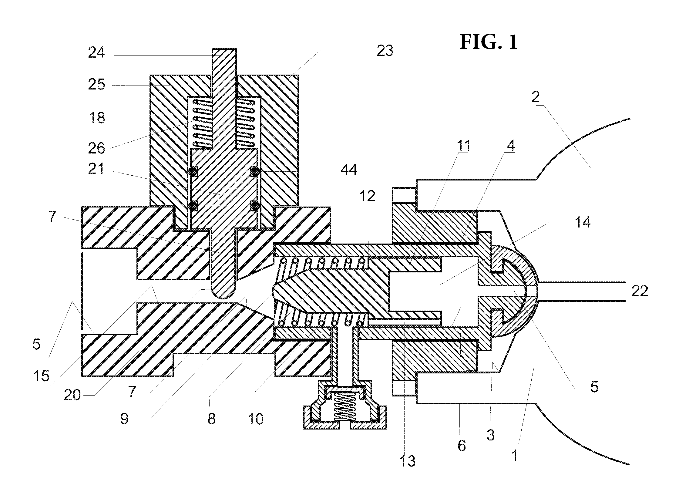
[0017]FIG. 1 shows a cross section of the device of this instant invention, wherein the a first piston is placed in its release position of the passage, e.g., without its end assuming a blocking or sealing position, while the resetting plunge...


PUM


Abstract

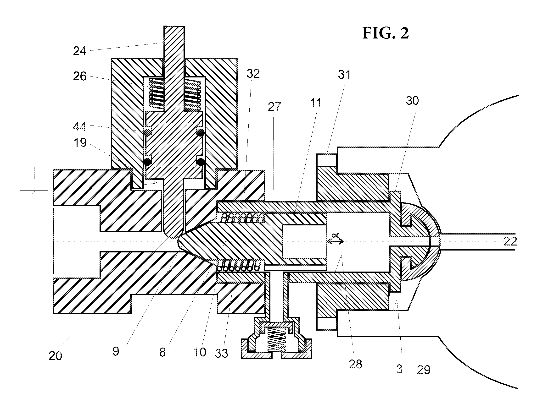
In a body, a first passage (6) houses a first piston (8) which is able to be selectively driven by the excess gas flow towards a blocking position and seal. The valve body has a second through-cut (17) intersecting the seal seat (7) of the first frustoconical piston (8). Within this second cut sits a second piston (21), pressing the end (20) thereof down against the end (9) of the protrusion of the first piston seal seat. This second piston (21) is capable of moving the second piston in interference with the end (9) upstream of the first piston seal eliminating the relationship with said seal seat.

Description

FIELD OF THE INVENTION[0001]The present invention is related to a safety valve placed in a fluid circuit between the source of said gas under pressure and the device or appliance to which said gas is being fed, such as, e.g.: a pressure gas regulator, a heater, a stove, etc. That is, the device of this instant invention is applied downstream of the outlet of a gas under pressure and placed in between said source of fluid and any device to which said gas under pressure is being supplied to.[0002]To be able to properly understand the corresponding amplitude and scope of this instant invention the following terms are given the following comprehensive definitions:[0003]GAS: This is the name given to all gasified fluids, either in their liquid state under pressure or in their gaseous state, also under pressure, such as GNC, LPG, domestic gas mains supplied by gas utilities, and industrial gasses such as oxygen, nitrogen, hydrogen, Freon, acetylene, argon, etc.[0004]FLUID SOURCE: This is ...

Claims


Application Information

Patent Timeline
Patent Type & Authority Patents(United States)
IPC IPC(8): F16K17/34F16K17/168F16K17/04
CPCF16K17/168F16K17/042Y10T137/7922
Inventor MUSTAFA, JORGE ISMAEL
Owner MUSTAFA JORGE ISMAEL
Learn More