Three-dimensional drift control apparatus and microscope apparatus

a control apparatus and three-dimensional drift technology, applied in the field of three-dimensional direction drift control apparatus and microscope apparatus, can solve the problems of micro-change of the observation position of the sample in the observation field of view, inability to be ignored, and difficulty in quickly and accurately correcting the misalignment. , to achieve the effect of quick and accurate correction

Active Publication Date: 2016-11-15
NIKON CORP
View PDF11 Cites 0 Cited by
  • Summary
  • Abstract
  • Description
  • Claims
  • Application Information

AI Technical Summary

Benefits of technology

[0011]With the foregoing in view, it is an object of the present invention to correct misalignment of the relative positions between an objective lens and a sample quickly and accurately.
[0015]According to the present invention, misalignment of the relative positions between the objective lens and the sample can be corrected quickly and accurately.

Problems solved by technology

However in the case of observation in the resolution range, a micro-change of the observation position of the sample in the observation field of view, generated by the mechanical drift of the apparatus and the thermal expansion of cover glass, which have not been major problems, cannot be ignored.
With the above mentioned prior art, however, if misalignment is generated in the relative positional relationship between the objective lens and the sample, it is difficult to quickly and accurately correct the misalignment.
In the case of the passive method, for example, the change of the relative positions between the objective lens and the sample can be compensated in three-dimensional directions, but if the brightness and contrast of the sample are low, image analysis takes time, and delay or an error occurs in focusing.
And in the case of the active method, the change of the relative positions between the objective lens and the sample in the plane direction cannot in theory be detected.

Method used


Image

  • Three-dimensional drift control apparatus and microscope apparatus
  • Three-dimensional drift control apparatus and microscope apparatus
  • Three-dimensional drift control apparatus and microscope apparatus

Examples


Embodiment Construction

[0019]Embodiments of the present invention will now be described with reference to the drawings.

[Configuration of Microscope]

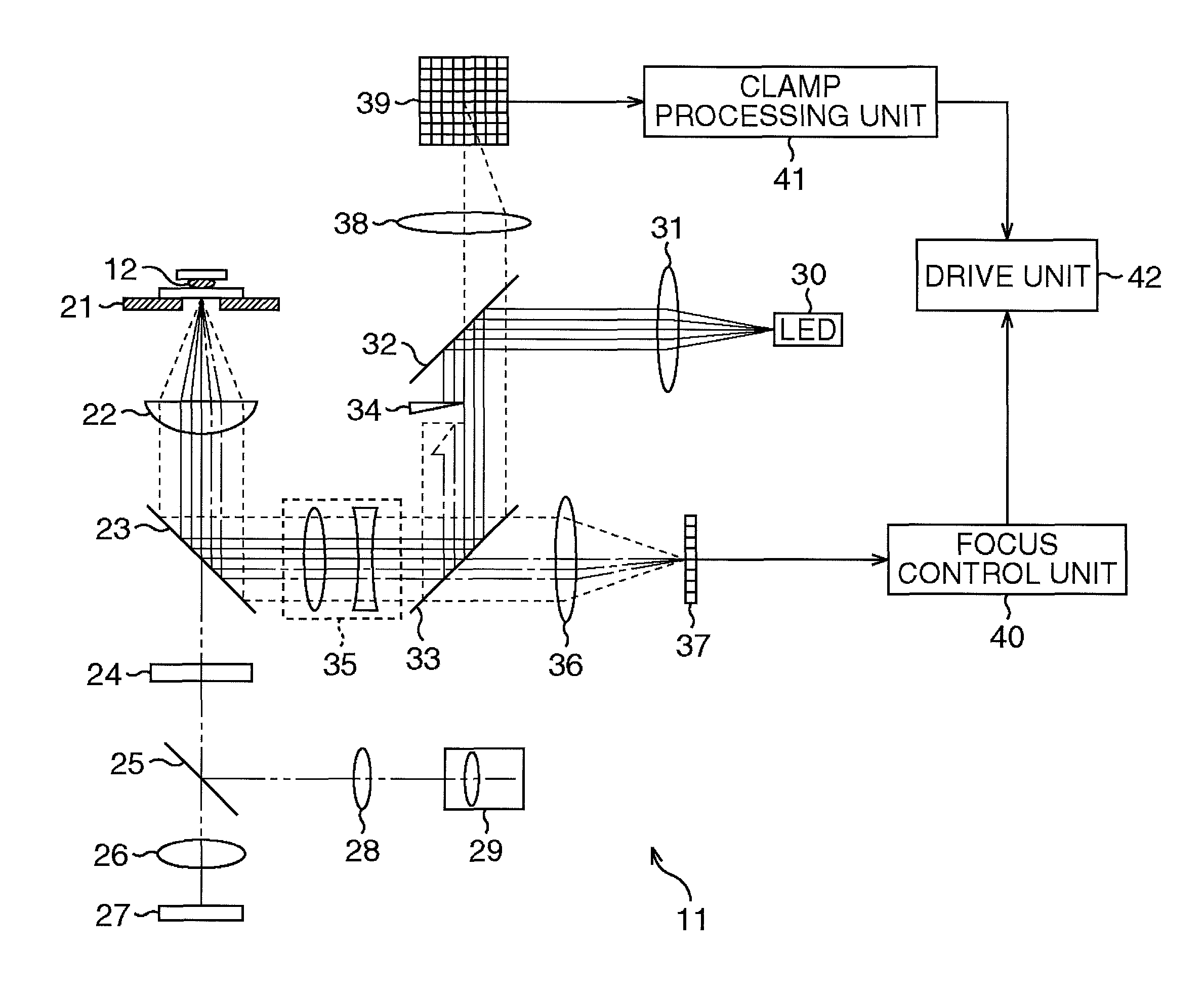
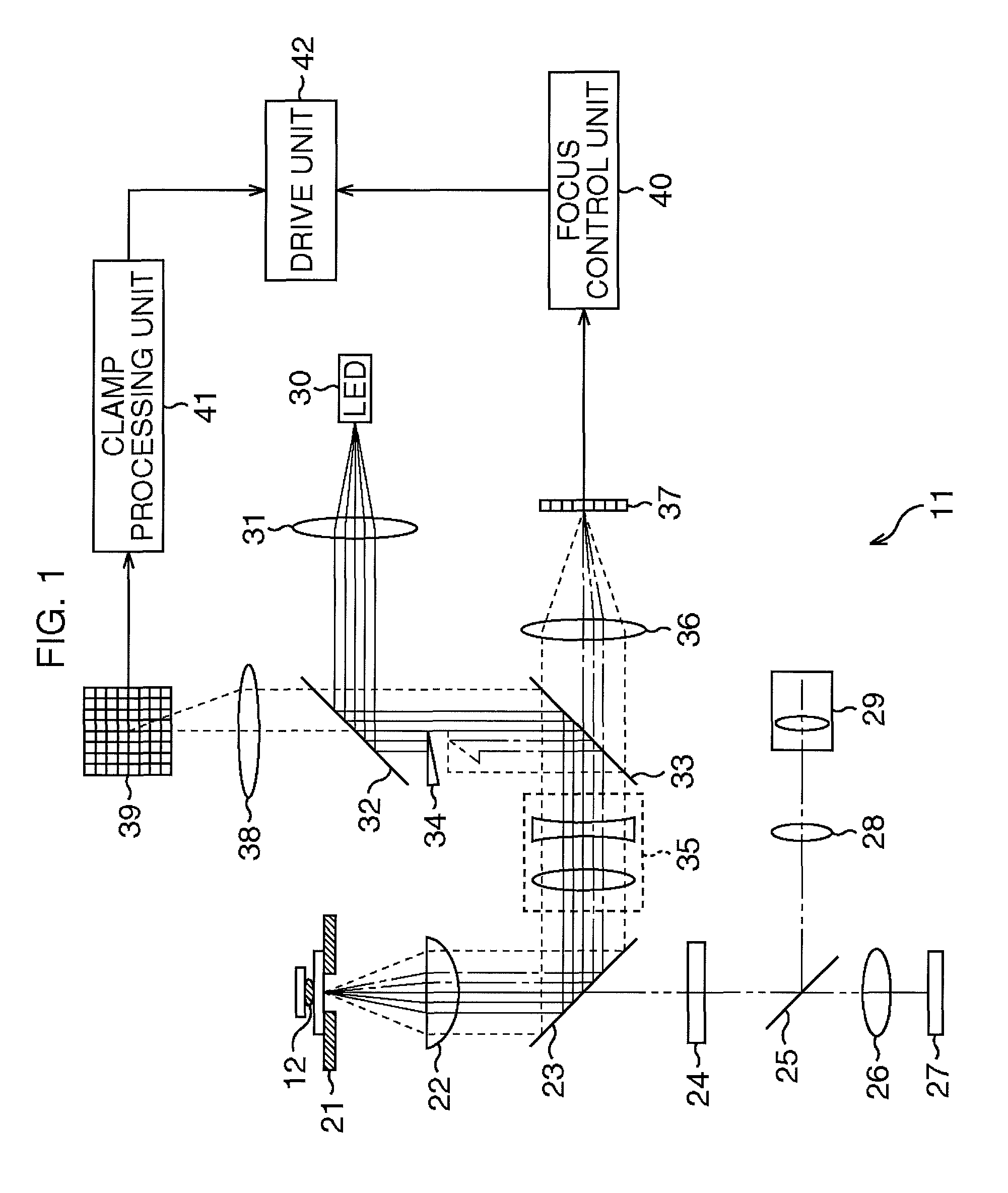
[0020]FIG. 1 is a configuration example of an embodiment of a microscope to which the present invention is applied.

[0021]A microscope 11 is an optical microscope for forming an enlarged image of an observation object sample 12 and observing the sample 12. The sample 12, which is emersed in such a medium as water, is between a cover glass and a slide glass, and is placed on a stage 21. The cover glass and the slide glass holding the sample 12 are also called “holding members other than observation object”.

[0022]An illumination apparatus (not illustrated) is installed on the microscope 11, and the illumination apparatus emits a visible light, which is an illumination light, and illuminates the sample 12. For example, if the illumination apparatus is a transmission type, the illumination apparatus is disposed above the stage 21 in FIG. 1, and if the illumination ...


PUM


Abstract

A three-dimensional direction drift control apparatus and a microscope apparatus that correct misalignment of a relative position between an object lens and a sample. A near-infrared light emitted from a light source is irradiated onto a surface of a glass cover holding a sample on a stage. When the near-infrared light is irradiated onto the glass cover, a regular reflection light and scattered light of the near-infrared light are generated, and the regular reflection light and the scattered light enter a half-mirror via lenses from an objective lens to an offset lens group. A clamp processing unit detects misalignment in the lateral direction of the object lens with respect to the sample based on the image of the scattered light, which has been reflected by the half-mirror and entered a two-dimensional photoelectric converter, and controls a drive unit according to this detection result, whereby the stage is moved.

Description

CROSS-REFERENCE TO RELATED APPLICATIONS[0001]This is a continuing application, filed under 35 U.S.C. §111(a), of International Application PTC / JP2010 / 061807, filed Jul. 13., 2010, which claims priority benefit of Japanese Application No. 2009-164388, filed Jul. 13, 2009, which are incorporated by reference herein in their entireties.TECHNICAL FIELD[0002]The present invention relates to a three-dimensional direction drift control apparatus and a microscope apparatus, and more particularly to a three-dimensional direction drift control apparatus and a microscope apparatus which can correct relative positions between an objective lens and a sample in a plane direction, quickly and accurately.BACKGROUND ART[0003]Lately the usefulness of a microscope having an auto focus function is becoming recognized in the market place. If the auto focus function of active control, for constantly focusing on a sample, is used, blur and movement of an observation image, generated during a time lapse ob...

Claims


Application Information

Patent Timeline
Patent Type & Authority Patents(United States)
IPC IPC(8): G02B21/36G02B23/00G02B21/26G02B21/24
CPCG02B21/26G02B21/245G02B21/365G02B21/06
Inventor NISHIKAWA, SO
Owner NIKON CORP
Why Eureka
Try Eureka