Three-dimensional drift control apparatus and microscope apparatus

Active Publication Date: 2012-08-02
NIKON CORP
View PDF3 Cites 16 Cited by
  • Summary
  • Abstract
  • Description
  • Claims
  • Application Information

AI Technical Summary

Benefits of technology

[0010]With the foregoing in view, it is an object of the present invention to correct misalignment of the relative positions between an objective lens and a sample quickly and accurately.
[0013]According to the present invention, misalignment of the relative positions between the objective lens and the sample can be corrected quickly and accurately.

Problems solved by technology

However in the case of observation in the resolution range, a micro-change of the observation position of the sample in the observation field of view, generated by the mechanical drift of the apparatus and the thermal expansion of cover glass, which have not been major problems, cannot be ignored.
With the above mentioned prior art, however, if misalignment is generated in the relative positional relationship between the objective lens and the sample, it is difficult to quickly and accurately correct the misalignment.
In the case of the passive method, for example, the change of the relative positions between the objective lens and the sample can be compensated in three-dimensional directions, but if the brightness and contrast of the sample are low, image analysis takes time, and delay or an error occurs in focusing.
And in the case of the active method, the change of the relative positions between the objective lens and the sample in the plane direction cannot in theory be detected.

Method used


Image

  • Three-dimensional drift control apparatus and microscope apparatus
  • Three-dimensional drift control apparatus and microscope apparatus
  • Three-dimensional drift control apparatus and microscope apparatus

Examples


first embodiment

[Configuration of Microscope]

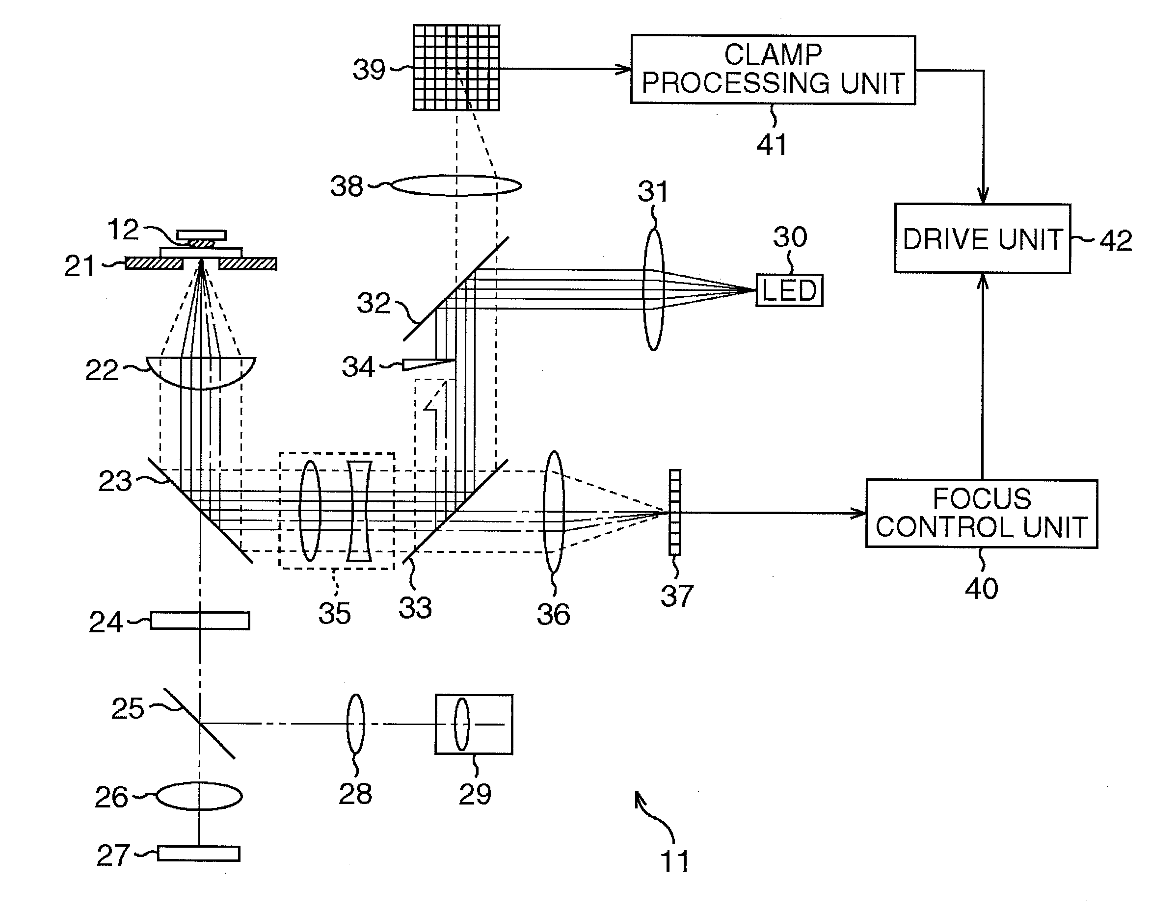
[0018]FIG. 1 is a configuration example of an embodiment of a microscope to which the present invention is applied.

[0019]A microscope 11 is an optical microscope for forming an enlarged image of an observation object sample 12 and observing the sample 12. The sample 12, which is emersed in such a medium as water, is between a cover glass and a slide glass, and is placed on a stage 21. The cover glass and the slide glass holding the sample 12 are also called “holding members other than observation object”.

[0020]An illumination apparatus (not illustrated) is installed on the microscope 11, and the illumination apparatus emits a visible light, which is an illumination light, and illuminates the sample 12. For example, if the illumination apparatus is a transmission type, the illumination apparatus is disposed above the stage 21 in FIG. 1, and if the illumination apparatus is an epi-illumination type, the illumination apparatus is disposed below the stage 21...

second embodiment

[Configuration of Microscope]

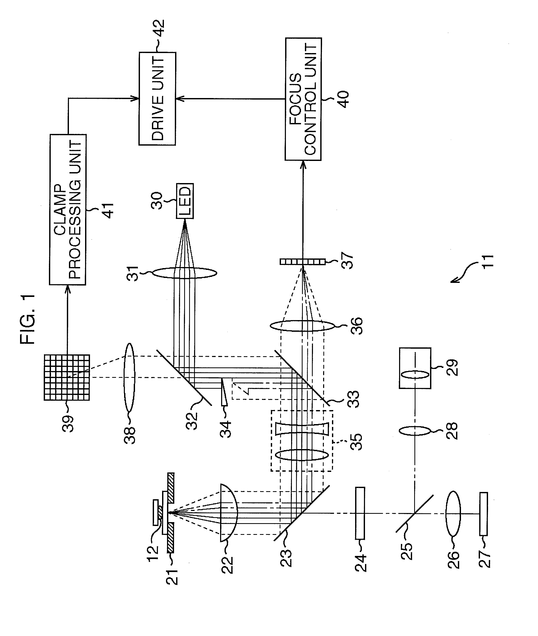
[0073]In the microscope 11, one picture element may alternately capture an image of the regular reflection light (slit image) and the scattering image. In this case, the microscope 11 is configured as illustrated in FIG. 2. In FIG. 2, a portion that corresponds to a portion in FIG. 1 is denoted with a same reference number, and description thereof is omitted unless necessary.

[0074]In the microscope 11 in FIG. 2, the lens 38, the two-dimensional photoelectric converter 39 and the clamp processing unit 41 in FIG. 1 are not installed, and a two-dimensional photoelectric converter 71 is installed instead of the line sensor 37 in FIG. 1. This two-dimensional photoelectric converter 71 is constituted by a CCD, among other components, and is disposed in a position that is conjugate with the image forming position of the near-infrared light irradiated onto the cover glass.

[0075]In the microscope 11, a knife edge 72, that shields the regular reflection light and ...

third embodiment

[Configuration of Microscope]

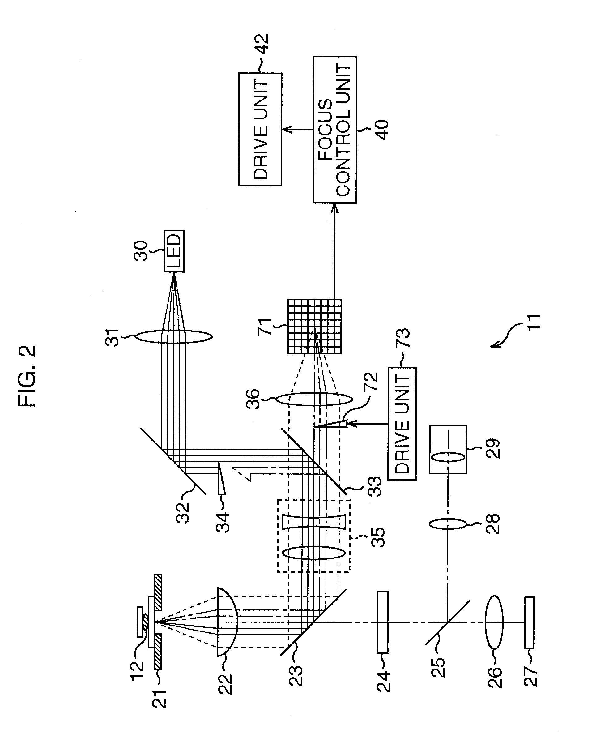
[0086]An example of using the near-infrared light to detect misalignment in the xy direction and in the z direction was described, but a light having a different wavelength may be used for each direction. In this case, the microscope 11 has the configuration illustrated in FIG. 3, for example. In FIG. 3, a portion that corresponds to a portion in FIG. 1 is denoted with a same reference number, and description thereof is omitted unless necessary.

[0087]In the microscope 11 in FIG. 3, a light source 101, which is constituted by an LD (Laser Diode) for example, and emits a reference light of which wavelength is different from that of the near-infrared light, is installed separately from the light source 30 for emitting the near-infrared light. The microscope 11 in FIG. 3 also includes a total reflection mirror 102 and a dichroic mirror 103.

[0088]The dichroic mirror 103 is disposed between the offset lens group 35 and the half-mirror 33, and separates the ref...


PUM


Abstract

A three-dimensional direction drift control apparatus and a microscope apparatus that correct misalignment of a relative position between an object lens and a sample. A near-infrared light emitted from a light source is irradiated onto a surface of a glass cover holding a sample on a stage. When the near-infrared light is irradiated onto the glass cover, a regular reflection light and scattered light of the near-infrared light are generated, and the regular reflection light and the scattered light enter a half-mirror via lenses from an objective lens to an offset lens group. A clamp processing unit detects misalignment in the lateral direction of the object lens with respect to the sample based on the image of the scattered light, which has been reflected by the half-mirror and entered a two-dimensional photoelectric converter, and controls a drive unit according to this detection result, whereby the stage is moved.

Description

TECHNICAL FIELD[0001]The present invention relates to a three-dimensional direction drift control apparatus and a microscope apparatus, and more particularly to a three-dimensional direction drift control apparatus and a microscope apparatus which can correct relative positions between an objective lens and a sample in a plane direction, quickly and accurately.BACKGROUND ART[0002]Lately the usefulness of a microscope having an auto focus function is becoming recognized in the market place. If the auto focus function of active control, for constantly focusing on a sample, is used, blur and movement of an observation image, generated during a time lapse observation over a long period of time, or when a reagent is administered into a container, can be effectively removed.[0003]There are roughly two types of methods for implementing the auto focus function are roughly divided: the passive method and the active method.[0004]In the case of the passive method, for example, a blur of an obs...

Claims


Application Information

Patent Timeline
IPC IPC(8): G02B21/06G02B21/36
CPCG02B21/245G02B21/365G02B21/26G02B21/06
Inventor NISHIKAWA, SO
Owner NIKON CORP
Why Eureka
Try Eureka