Wall mount for a shower system

a shower system and wall mount technology, applied in the field of wall mounts for shower systems, can solve problems such as leakage at the point of connection or the wall connection itself, and achieve the effects of simple surface structure, good configuration option, and compact design

Active Publication Date: 2016-11-29
GROHE
View PDF12 Cites 6 Cited by
  • Summary
  • Abstract
  • Description
  • Claims
  • Application Information

AI Technical Summary

Benefits of technology

[0009]In an embodiment of the invention, two or more wall connections, adapter pieces, and conduit are provided. Whereas it is sufficient in especially simple embodiments to run mixed water lines from the wall connection through the shower system, for example, two line systems for cold and warm water can be present as a wall connection in other applications. In this case, the bracket is designed, for example, so that it has two adapter pieces for connecting two wall connections and over the further course then also two separate conduits in order to convey the incoming water streams within the shower system, for example, further to a mixer or thermostat. In this type of design as well, there would be the advantage of the invention that the mechanical load of the wall connections is eliminated and the mechanical strength of the wall mount is considerably improved.
[0010]Accordingly, it is advantageous in other refinements of the present invention if at least one flow restrictor, pressure stabilizer, temperature limiter, or pressure limiter is disposed in the adapter piece. In this way, depending on the technical and legal requirements of the particular location of the shower system, additional functionalities can already be integrated into the wall mount. This results in an especially compact design and permits an especially good configuration option.
[0011]In an embodiment of the invention, at least one top and one bottom bracket are provided, whereby the top bracket is connected to the overhead wall connection. In certain regions, overhead wall connections are installed preferentially. In this case, a shower system can be retrofitted especially easily in already existing wall connections with the wall mount of the invention and the aforementioned advantages of the present invention can be realized simultaneously.
[0012]In order to enable the desired allowable relative movement between the bracket and adapter piece, it has proven especially advantageous, moreover, if the sealing component is configured as an elastic rubber ring. In an especially simple embodiment, this can be a rubber ring with a circular profile cross section. In other embodiments, however, a plurality of rings can also be used arranged axially one behind the other. In addition, the profile of the elastic rubber ring is not limited exclusively to a circular cross section. Rather, all known cross section forms of seals can be used in relation to the present invention.
[0013]Because the demands in regard to the design forms of shower systems are subject to high requirements, it is advantageous, furthermore, if the bracket covers the adapter piece at least in the visible area. Thus, it is possible to provide only the bracket with suitably high-quality visible surfaces and to furnish the adapter piece with more reasonably priced simple surfaces, as a result of which cost savings are achieved during production.
[0014]To assure the reliable functionality of the invention, it is provided in further embodiments that a structural minimum distance or minimum gap can be provided continuously between the bracket and the adapter piece, except for the area of the sealing component. The structural minimum distance is selected, for example, so that it is greater than the deformation paths maximally allowable by the provided sealing component. The direct contact between the adapter piece and bracket and thereby a direct force transmission can be avoided in this way. Basically, it applies in the selection of the minimum distance that the greater this distance is selected, the more the force application by the bracket to the adapter piece can be reduced. If for various reasons it is necessary to select a small minimum distance, at least versus the state of the art a considerable reduction of force application can be achieved.

Problems solved by technology

A disadvantage in such prior-art systems is that because of changing loads relative movements between the wall connection and the shower system can arise, which in the long run can lead to leaking at the point of connection or the wall connection itself.

Method used


Image

  • Wall mount for a shower system
  • Wall mount for a shower system
  • Wall mount for a shower system

Examples


Embodiment Construction

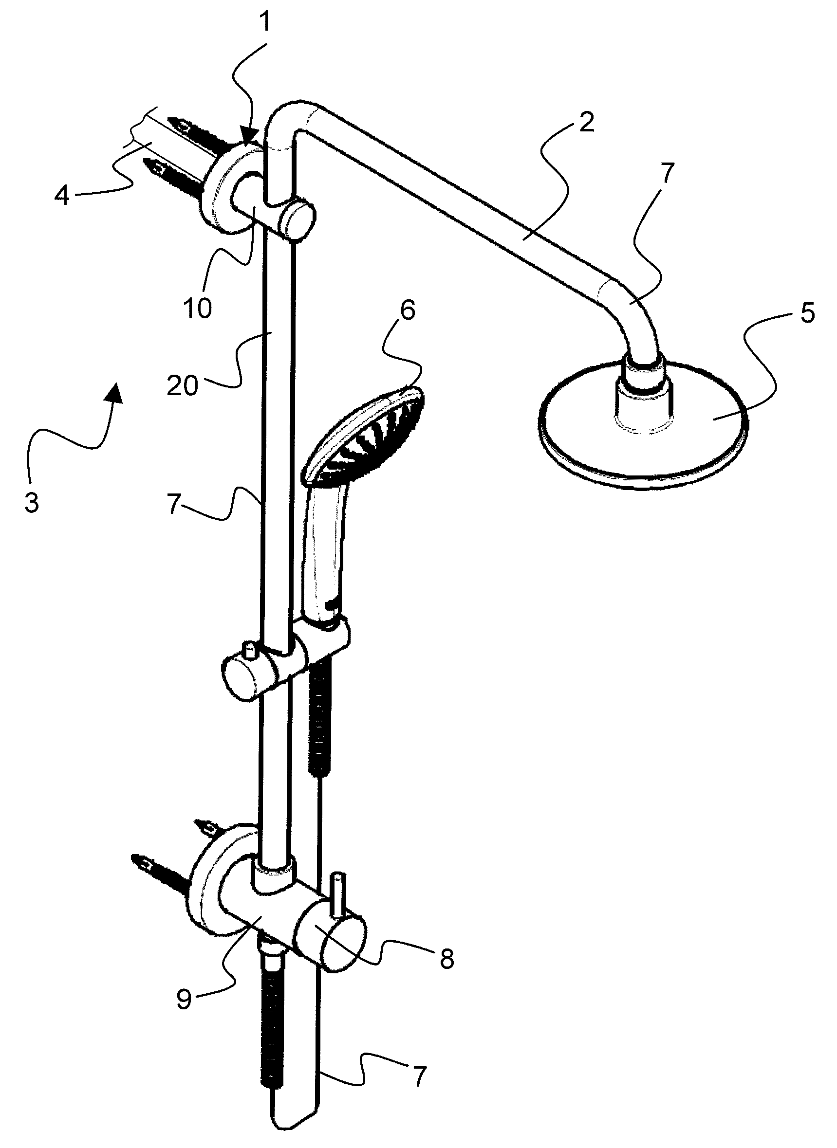
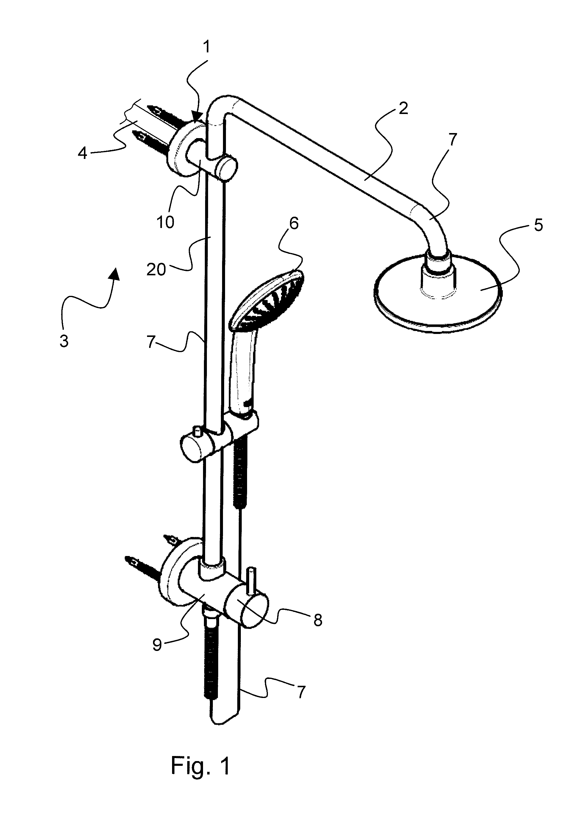
[0025]A wall mount 1 of the invention for a shower system 2 is illustrated in an oblique view in FIG. 1, whereby in this view shower system 2 is attached to a wall 3, from which a wall connection 4 emerges. Wall connection 4 in the shown embodiment is formed as a mixed water outlet through which water with the desired temperature is provided.

[0026]Shower system 2 comprises further a shower rod 20, an overhead shower head 5, and a hand shower 6, which are connected via a conduit 7 to a changeover device 8. Changeover device 8 is disposed in a bottom bracket 9, which for its part is connected via conduit 7 to a top bracket 10.

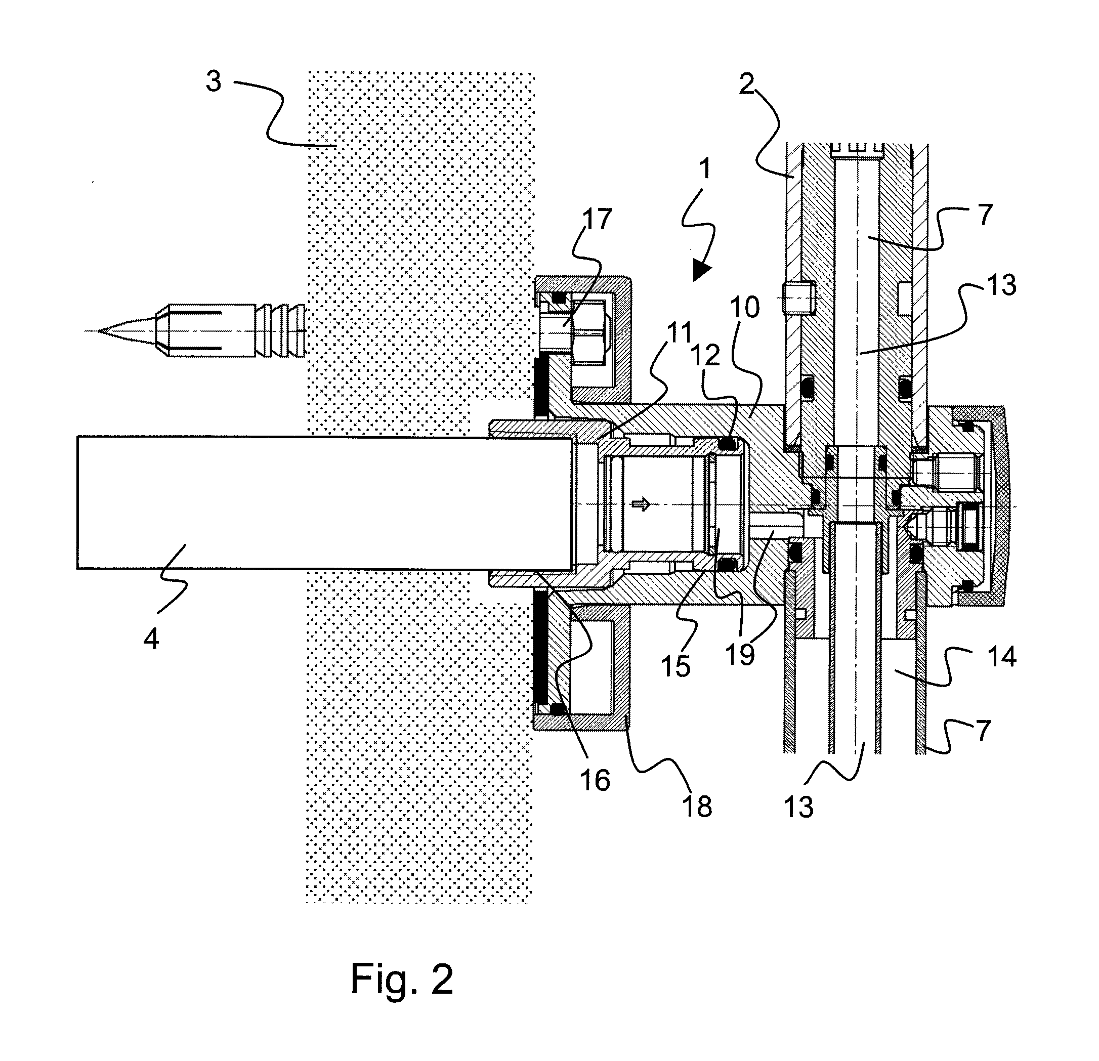
[0027]Top bracket 10 is illustrated in a sectional view in FIG. 2. The conduit 7, which conveys water alternatively to overhead shower head 5 or to hand shower 6, runs through bracket 10. In the illustrated embodiment, the conduit 7 in the top section above top bracket 10 has a first conduit channel 13, whereas in the bottom section below it comprises two separat...


PUM


Abstract

A wall mount for a shower system at a wall connection emerging from a wall, whereby the shower system has at least one overhead shower head, a hand shower, and a shower rod. The attachment has at least one bracket with at least one conduit connected thereto and at least one adapter piece, whereby the bracket is configured to accommodate the adapter piece and a seal is provided between bracket and adapter piece, the seal allowing a relative movement between the bracket and adapter piece. The adapter piece is connectable to the wall connection by a first connecting component and the bracket is connected to the wall by a second connecting component. The bracket together with the adapter piece forms at least one conduit path between the wall connection and the conduit.

Description

[0001]This nonprovisional application claims priority under 35 U.S.C. §119(a) to German Patent Application No. DE 10 2012 008 406.4, which was filed in Germany on Apr. 27, 2012, and which is herein incorporated by reference.BACKGROUND OF THE INVENTION[0002]Field of the Invention[0003]The present invention relates to a wall mount for a shower system at a wall connection emerging from a wall, whereby the shower system comprises at least one overhead shower head, a hand shower, and a shower rod. Further, the present invention relates to a method for installing a shower system on a wall mount. The invention is used in sanitary facilities and here particularly in showers and baths.[0004]Description of the Background Art[0005]U.S. Pat. No. 7,043,776 B1 discloses a shower system with an overhead wall connection. A wall mount, which is screwed together directly with the wall connection, is provided for attaching the prior-art shower system. A disadvantage in such prior-art systems is that b...

Claims


Application Information

Patent Timeline
Patent Type & Authority Patents(United States)
IPC IPC(8): E03C1/042E03C1/06E03C1/04
CPCE03C1/06E03C1/0408
Inventor SCHULTE, MICHAEL
Owner GROHE
Why Eureka
Try Eureka