Wall assembly

a wall and foam technology, applied in the field of wall assemblies, can solve the problems of damage to the outer rigid foam layer and lack of thermal breakage of the wall assembly, and achieve the effect of increasing the strength of the wall assembly

Active Publication Date: 2017-12-28
BASF AG
View PDF20 Cites 8 Cited by
  • Summary
  • Abstract
  • Description
  • Claims
  • Application Information

AI Technical Summary

Benefits of technology

[0005]A wall assembly is manufactured for supporting an exterior coving of a structure. The wall assembly includes a frame assembly. The frame assembly includes a top member having a top interior surface configured to face an interior of the structure and a top exterior surface configured to face an exterior of the structure. The frame assembly also includes a bottom member spaced from the top member. The bottom member has a bottom interior surface configured to face the interior of the structure and a bottom exterior surface configured to face the exterior of the structure. The frame assembly further includes a plurality of vertical members spaced from each other and coupled to and extending between the top and bottom members. The plurality of vertical members each have an outer surface configured to face the exterior of the structure. A rigid foam layer is directly coupled to the outer surface of the plurality of vertical members. A sheathing layer is coupled to the rigid foam layer opposite the plurality of vertical members with the sheathing layer configured to receive the exterior covering. Because the rigid foam layer is between the sheathing layer and the frame assembly, the rigid foam layer provides a thermal break between the sheathing layer and the frame assembly within the wall assembly. Additionally, because the sheathing layer is coupled to the rigid foam layer, the sheathing layer increases a strength of the wall assembly.

Problems solved by technology

Because the exterior rigid foam layer is on the exterior of the sheathing layer, the exterior rigid foam layer may become damaged during handling and installation of the wall assembly.
Additionally, because the sheathing layer is directly connected to the frame assembly and is between the exterior rigid foam layer and any interior rigid foam layer, the wall assembly lacks a thermal break to prevent the flow of thermal energy from the sheathing layer through the frame assembly.

Method used


Image

  • Wall assembly
  • Wall assembly
  • Wall assembly

Examples


Embodiment Construction

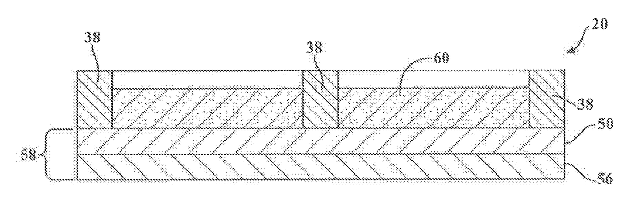
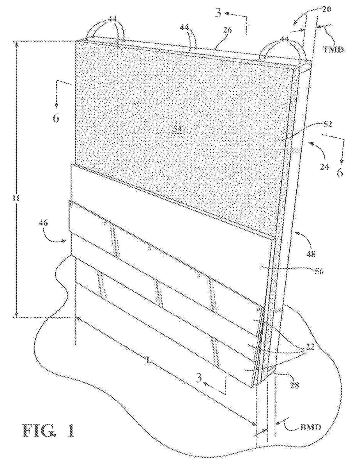
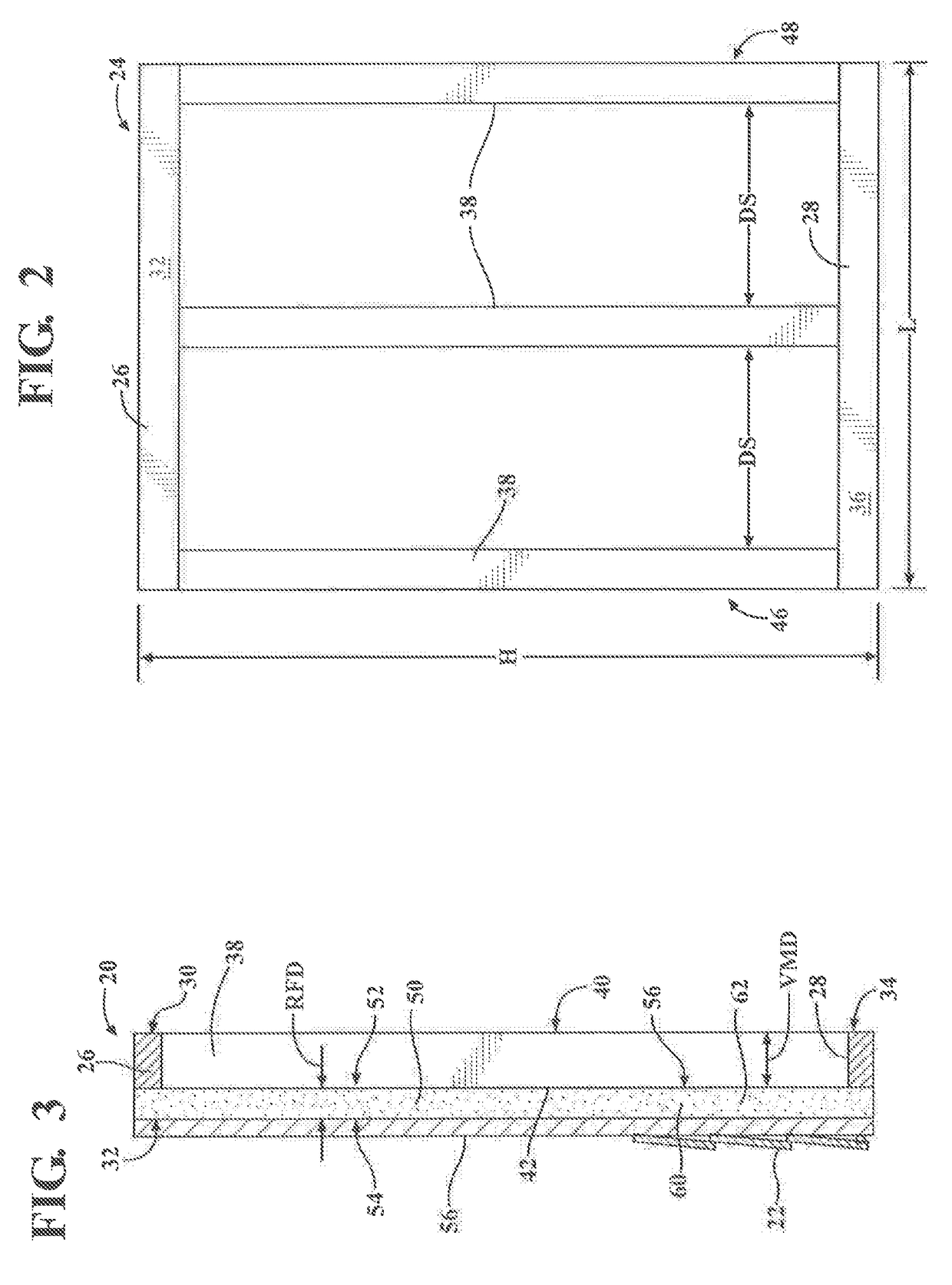
[0016]Referring to the Figures, wherein like numerals indicate corresponding parts throughout the several views, a wall assembly is generally shown at 20. The wall assembly 20 is for constructing a building, such as a residential building or a commercial building. For example, the wall assembly 20 is at least one of a plurality of exterior walls of the building. It is to be appreciated that the wall assembly 20 may only be one of the plurality of exterior walls of the building or the wall assembly 20 may be all of the plurality of exterior walls of the building. Said differently, the wall assembly 20 may be used to construct a single exterior wall of the building.

[0017]Alternatively, multiple wall assemblies 20 may be used to construct the exterior walls of building. Said differently, the wall assembly 20 may be coupled to another wall assembly 20 to define a perimeter of the building. Additionally, the wall assembly 20 may be coupled to a traditional field constructed wall to defin...


PUM

PropertyMeasurementUnit
thicknessaaaaaaaaaa
heightaaaaaaaaaa
heightaaaaaaaaaa

Abstract

A wall assembly is manufactured for supporting an exterior covering of a structure. The wall assembly includes a frame assembly including a top member and a bottom member spaced from the top member. The frame assembly further includes a plurality of vertical members spaced from each other and coupled to and extending between the top and bottom members. The plurality of vertical members each have an exterior surface configured to face an exterior of the structure. A rigid foam layer is directly coupled to the exterior surface of the plurality of vertical members. A sheathing layer is coupled to the rigid foam layer opposite the plurality of vertical members with the sheathing layer configured to receive the exterior covering.

Description

CROSS-REFERENCE TO RELATED APPLICATION(S)[0001]The present application claims the benefit of pending U.S. Provisional Patent Application, Ser. No. 62 / 104,948, filed Jan. 19, 2015, the entire disclosure of which is hereby incorporated by reference.BACKGROUND OF THE INVENTION1. Field of the Invention[0002]The present invention generally relates to a wall assembly.2. Description of the Related Art[0003]Wall assemblies for use as walls of a building, such as residential buildings, or commercial buildings, are known in the art. The conventional wall assembly includes a frame assembly. Generally, a sheathing layer is applied to the frame assembly and an exterior rigid foam layer is applied to the exterior of the sheathing layer. Because the exterior rigid foam layer is on the exterior of the sheathing layer, the exterior rigid foam layer may become damaged during handling and installation of the wall assembly. Additionally, because the sheathing layer is directly connected to the frame as...

Claims


Application Information

Patent Timeline
Patent Type & Authority Applications(United States)
IPC IPC(8): B32B3/08B32B5/18E04C2/288B32B3/18E04C2/38
CPCB32B3/085E04C2/288B32B5/18B32B2419/00B32B3/18B32B2607/00E04C2/386B32B3/08B32B3/10E04B2002/0273E04B2/02
Inventor FOX, PAUL J.CAMPBELL, PAUL
Owner BASF AG
Why Eureka
Try Eureka