Simplified non-polystyrene permanent insulating concrete form building system

a technology of non-polystyrene insulating concrete and building system, which is applied in the direction of walls, building components, building repairs, etc., can solve the problems of hygroscopic wood concrete wall system, little or nothing to interlock successive courses of wood wall, and the wall system “breathes” and other problems, to achieve the effect of enhancing the structural performance of the final wall structure, enhancing the strength and stability of the wall, and enhancing thermal properties

Inactive Publication Date: 2012-04-05
NYLIN MICHAEL EDWARD
View PDF99 Cites 6 Cited by
  • Summary
  • Abstract
  • Description
  • Claims
  • Application Information

AI Technical Summary

Benefits of technology

[0023]Additional shortcomings of the prior art are overcome and additional advantages are provided through the provision of a non-polystyrene insulating concrete wall form building system comprised of a wall form which has self-aligning ribs on the bottom of the forms and grooves to receive the ribs on the top of the forms, thereby providing a means of locking successive courses of forms together thus strengthening and stabilizing the wall system against unforeseen lateral forces applied to the wall system prior to filling the forms with concrete.
[0024]Additional shortcomings of the prior art are overcome and additional advantages are provided through the provision of a non-polystyrene insulating concrete wall form building system comprised of a wall form which includes a mechanism for clamping adjacent wall forms tightly together within the courses of the wall, thereby enhancing wall strength and stability against any unforeseen lateral forces applied to the wall system prior to filling the forms with concrete.
[0025]Additional shortcomings of the prior art are overcome and additional advantages are provided through the provision of a non-polystyrene insulating concrete wall form building system comprised of a wall form which includes, a mechanism for precisely positioning horizontal and vertical concrete reinforcement bars within the form, thereby enhancing the structural performance of the final wall structure.
[0026]Additional shortcomings of the prior art are overcome and additional advantages are provided through the provision of a non-polystyrene insulating concrete wall form building system comprised of a wall form, the geometry of the wall form's vertical cores and middle web being such that the forms may be stacked longitudinally in both running bond and stack bond configurations while ensuring that no air pockets, ledges or otherwise incomplete concrete fill occurs within the forms' cores.
[0027]Additional shortcomings of the prior art are overcome and additional advantages are provided through the provision of a stack bond configuration transverse to the more conventional longitudinal direction in cases where, a thicker, “super insulated” wall assembly might be desired for climates that have extreme temperatures. This orientation of the forms 90° to the longitudinal orientation provide enhanced thermal properties for the wall assembly due to the greater depth of insulation in the outside cores. In an exemplary embodiment of the present invention, because of the non-polystyrene insulating concrete form's unique proportions and smooth-ended geometry, this transverse orientation is possible without disrupting the required alignment of form cores required for proper structural performance.
[0028]Additional shortcomings of the prior art are overcome and additional advantages are provided through the provision of, from logistical and customer value perspectives, a palletized shipping configuration of insulating concrete forms which is more dense and less prone to form breakage as a result of the present invention smooth end configurations.

Problems solved by technology

Furthermore, the wood concrete wall system is hygroscopic, that is, the wall system “breathes”, taking on and giving off water vapor as it seeks ambient humidity levels.
While this type of end configuration may provide a limited degree of interlocking of forms on a particular course within the wall, it does little or nothing at all to interlock successive courses in the wall together.
As such, even with the interlocking end configuration, an accidental bumping of the wall by a construction worker or a piece of construction machinery can severely misalign the wall assembly prior to its being filled with reinforced concrete.
Such use of asymmetrical, male-female ends on the forms creates two major disadvantages for wall assembly.
Such mistakes made by construction workers in this regard require additional handling by the worker to re-orient the form properly, thereby increasing worker fatigue.
Secondly, at wall openings such as at doors and windows, the male-female end of the form located at the jamb (i.e., the side of the opening) of a door or window has to be smoothed by sawing, sanding or some other alternative course of action before window or door installation may proceed.
This also can slow down the assembly of the wall.
While the use of a male-female end configuration may offer some limited resistance to lateral movement which might occur in an accidental bumping of the wall during its construction or while waiting for the wall to be filled with concrete, the disadvantages of incomplete, multi-axis lateral stability in terms of bumping resistance, the possibility of mis-orientation of the form and the aforementioned required additional cutting or smoothing of the form at door and window jambs are serious drawbacks to an efficient construction process.
As is the case with the FASWALL form, this can have a significant negative constraining impact on the overall design of the building and / or the ease of construction if the dimensions of the corner forms do not readily conform to the overall design module of the construction project.
This violation of design modularity will frequently require additional cutting of forms at the construction site.
Accordingly, the precise location and / or orientation of the steel within the core and / or relative to other reinforcement bars within the form simply cannot often be assured.

Method used


Image

  • Simplified non-polystyrene permanent insulating concrete form building system
  • Simplified non-polystyrene permanent insulating concrete form building system
  • Simplified non-polystyrene permanent insulating concrete form building system

Examples


Embodiment Construction

[0080]Use of the term ‘course’, in the present invention and as used in the building trade, is intended to mean a continuous and usually horizontal range of brick, shingles, non-polystyrene insulated concrete forms, or other materials as in a wall, roof, or other structure.

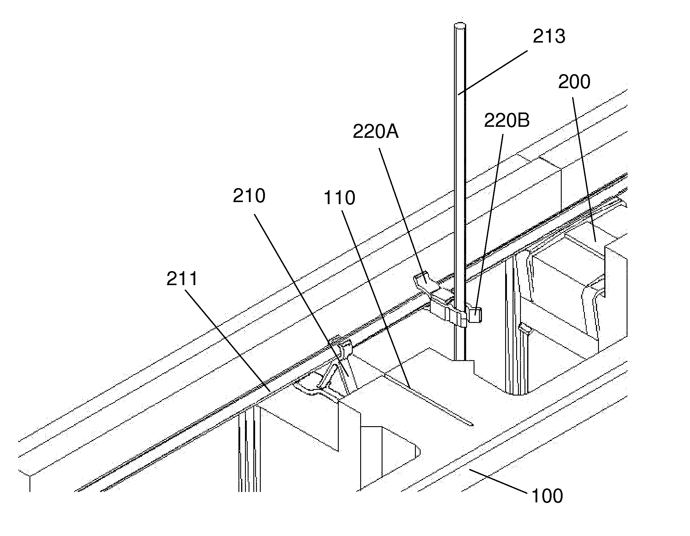
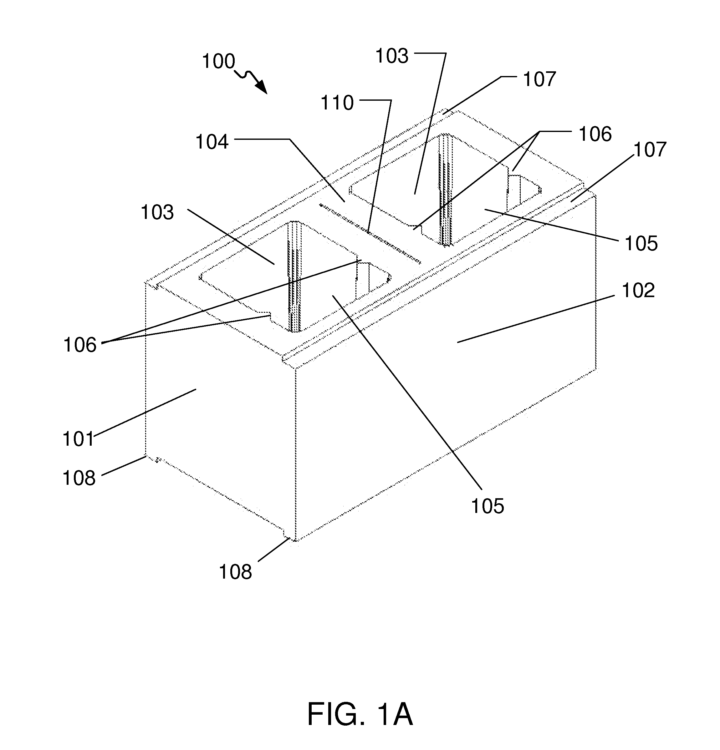
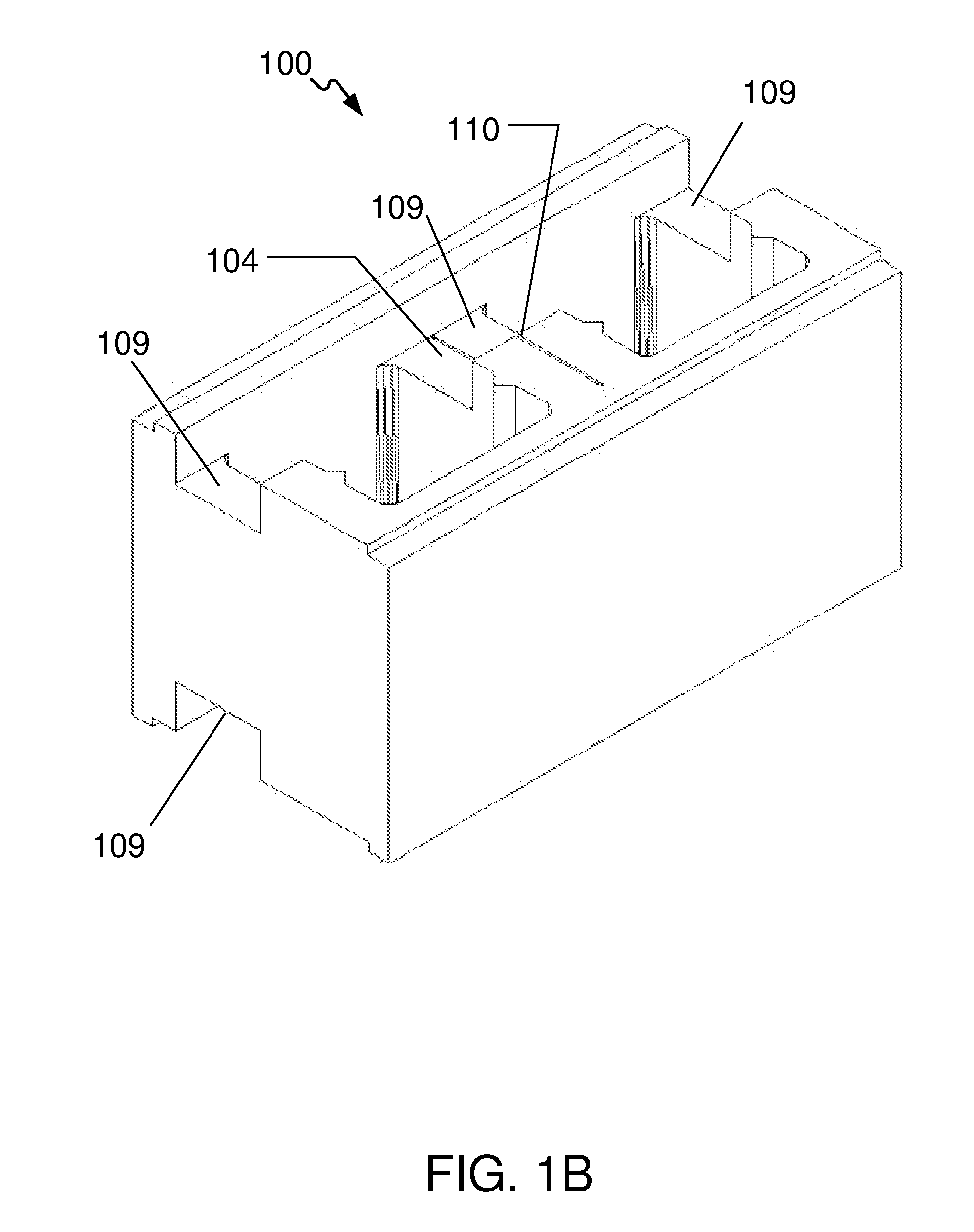
[0081]Turning now to the drawings in greater detail, it will be seen that in FIGS. 1A-1J there are illustrated examples of the non-polystyrene insulated concrete form which is part of the simplified non-polystyrene permanent insulating concrete form building system.

[0082]In an exemplary embodiment the simplified insulating concrete form building system is illustrated in FIGS. 1A to 1J. Referring to FIG. 1A there is illustrated one example of a non-polystyrene insulated concrete form 100 further comprising smooth non-articulated end faces 101, smooth non-articulated side walls 102, vertical cores 103, double middle web 104 with its middle web integral slot 110 which extends across the non-polystyrene insulated conc...


PUM

PropertyMeasurementUnit
angleaaaaaaaaaa
anglesaaaaaaaaaa
distanceaaaaaaaaaa

Abstract

A simplified insulating concrete form building system comprised of forms made from wood chips or other organic fibers, embedded in a Portland cement matrix, molded and trimmed into various shapes and sizes. The forms are held in position within the wall by means of unique, simplified form geometry and an internal fastening clip which combine to improve alignment and stability of the wall prior to filling the forms with concrete. The simplified geometry reduces worker error in orienting the form correctly within the wall thereby reducing handling and corresponding fatigue. The form's smooth faces provide more compact palletized shipments of forms, thereby reducing cost and damage in shipment. Concrete reinforcement bars are held within forms using a system of reinforcement bar holders which enables the precise positioning of the reinforcement within the wall, thereby increasing speed and accuracy of construction as well as structural performance of the wall assembly.

Description

CROSS-REFERENCE TO RELATED APPLICATIONS[0001]This application contains subject matter which is related to the subject matter of the following co-pending application. Each of the below listed applications is hereby incorporated herein by reference in its entirety:[0002]The present application is a continuation-in-part of an application entitled “SIMPLIFIED NON-POLYSTYRENE PERMANENT INSULATING CONCRETE FORM BUILDING SYSTEM”, Inventor Michael Edward Nylin, filed Sep. 18, 2007, Ser. No. 11 / 901,517; which is a non-provisional application that claims the benefit of provisional patent application entitled “A SIMPLIFIED NON-POLYSTYRENE PERMANENT INSULTING CONCRETE FORM BUILDING SYSTEM”, Inventor Michael Edward Nylin, filed Sep. 19, 2006, Ser. No. 60 / 845,607.TECHNICAL FIELD OF THE INVENTION[0003]This invention relates an improved, strong, non-polystyrene insulating concrete form building system which is comprised of a simplified form geometry with smooth, non-articulated ends and side walls,...

Claims


Application Information

Patent Timeline
Patent Type & Authority Applications(United States)
IPC IPC(8): E04B2/86E04C2/20E04C5/20
CPCE04B2/30E04B2/40E04B2/8629E04C5/20E04B2002/867E04B2002/8676E04C5/167E04B2002/0206
Inventor NYLIN, MICHAEL EDWARD
Owner NYLIN MICHAEL EDWARD
Why Eureka
Try Eureka