
Femoral knee prosthesis with diverging lateral condyle

a lateral condyle and femoral knee technology, applied in the field of orthopaedic prostheses, can solve problems such as femoral rollback, and achieve the effect of facilitating lateral condyle rollback

Active Publication Date: 2017-05-30
ZIMMER GMBH
View PDF93 Cites 4 Cited by
  • Summary
  • Abstract
  • Description
  • Claims
  • Application Information

AI Technical Summary

Benefits of technology

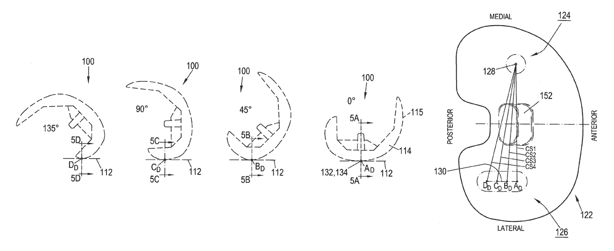
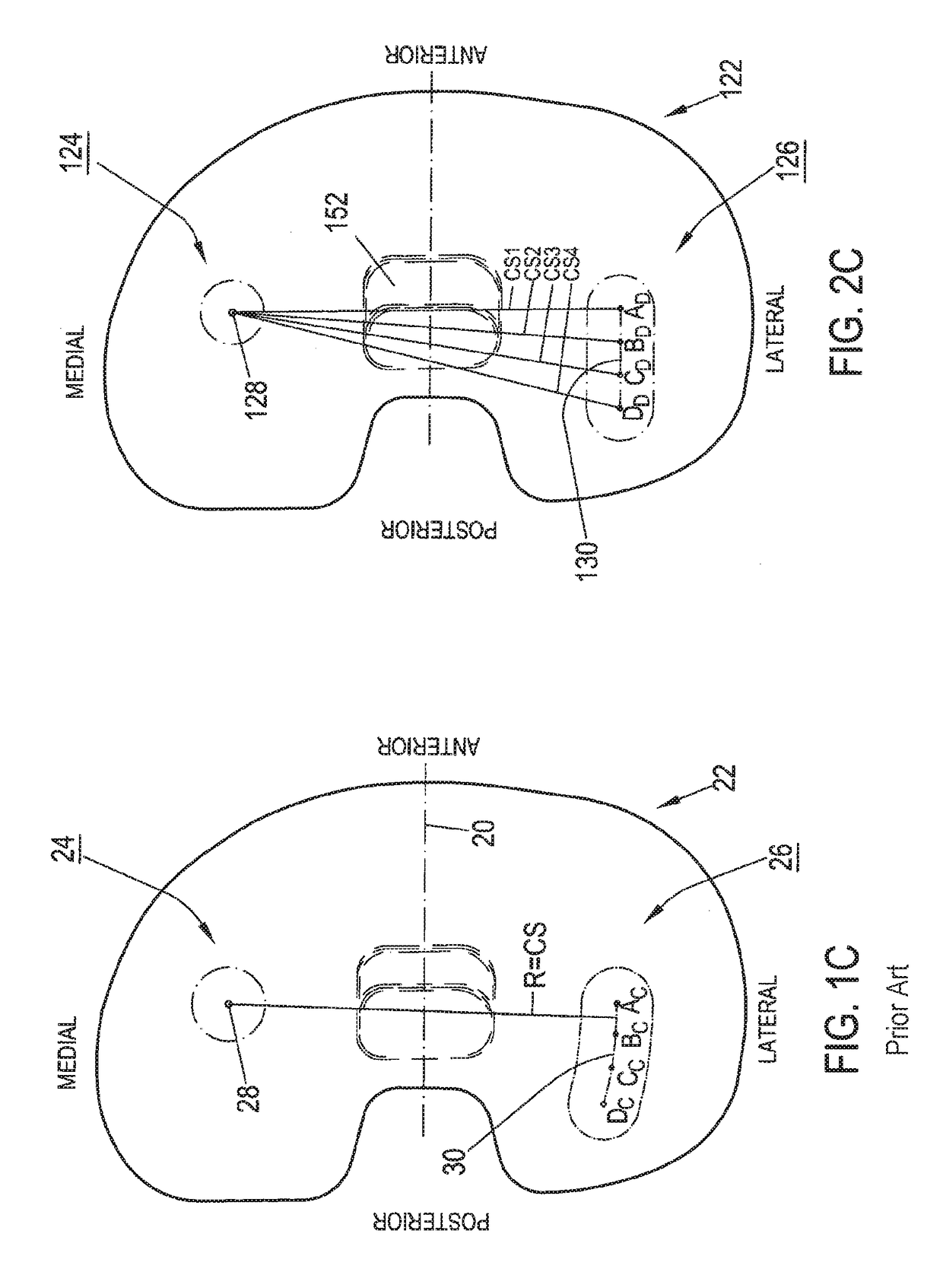
[0013]Advantageously this linear anteroposterior articulation profile accommodates and facilitates rollback of the lateral condyle arising from external rotation of the femoral component in deep flexion, and thereby ensures consistent, large-area contact between the articular surfaces of the femoral and tibial component throughout a wide flexion range.

Problems solved by technology

Femoral rollback results from the natural tendency of the tibia and femur to rotate relative to one another, about their longitudinal axes, as the knee progresses from extension to deep flexion.

Method used


Image

  • Femoral knee prosthesis with diverging lateral condyle
  • Femoral knee prosthesis with diverging lateral condyle
  • Femoral knee prosthesis with diverging lateral condyle

Examples


Embodiment Construction

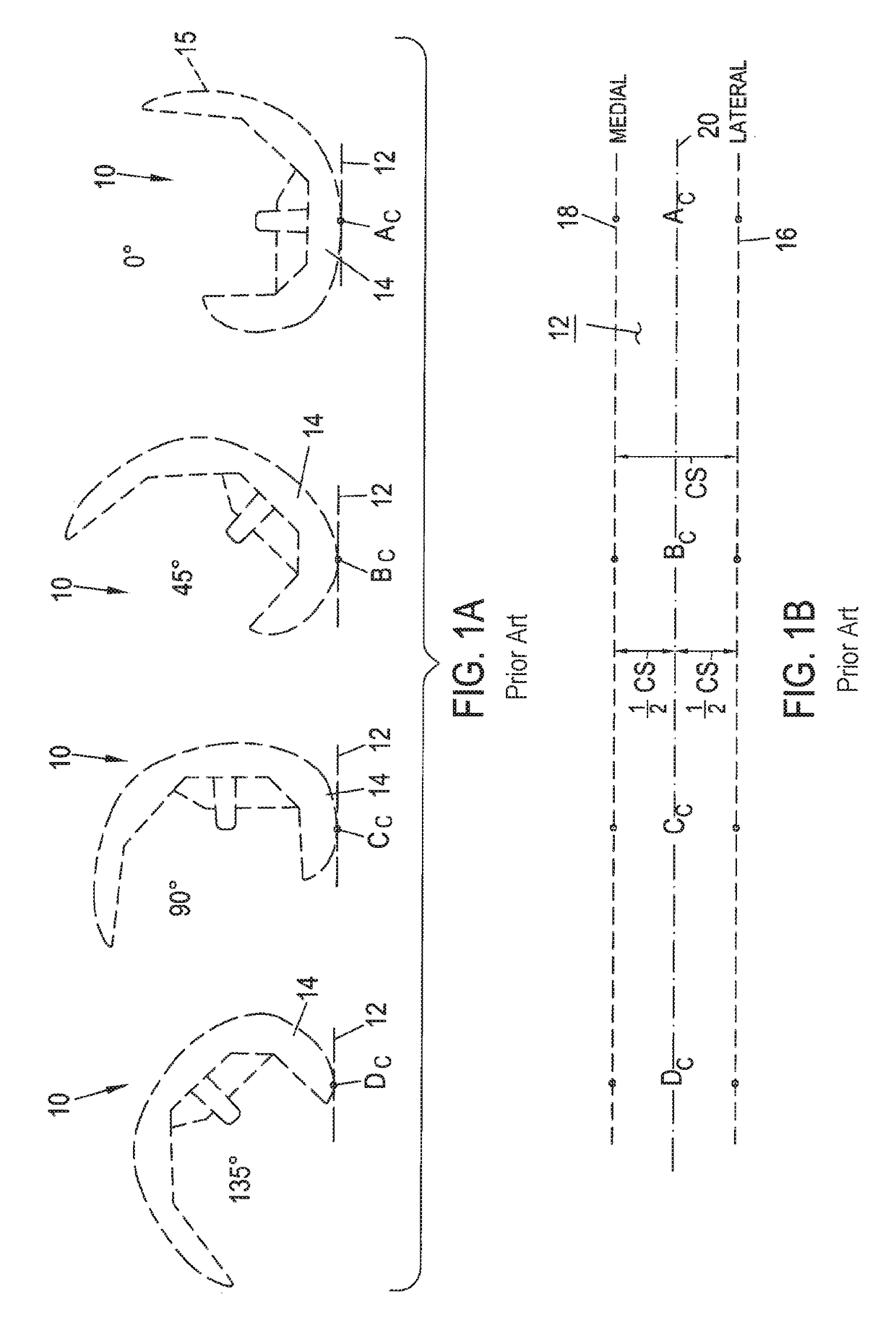
[0034]Turning to FIG. 1A, one type of femoral component 10 is shown from a sagittal viewpoint, with component 10 resting on flat surface 12. When component 10 is oriented in a position corresponding to zero degrees flexion, as shown on the right side of FIG. 1A, component 10 defines contact point AC between flat surface 12 and the distal-most point on the articular surface of lateral femoral condyle 14. As component 10 is rolled along flat surface 12 to position corresponding to about 45° flexion, femoral component 10 defines contact point BC between lateral condyle 14 and flat surface 12. Similarly, as femoral component 10 is rolled further upon flat surface 12 to positions corresponding to 90° flexion and 135° flexion, contact points CC and DC are respectively defined between respective posterior portions of condyle 14 and flat surface 12.

[0035]Applicants refer to contact “points” herein in the context of contact between femoral and tibial components. While it is appreciated that ...


PUM


Abstract

A knee prosthesis has a femoral component with a medial condyle defining a constant bearing spacing relative to a central sagittal component plane SP, and a lateral condyle defining divergent bearing spacing from the central sagittal component plane along an extension-to-flexion path. High congruence between the medial articulation surfaces creates a pivot point for external rotation at the medial contact area, while lower congruence in the lateral articulation surfaces allows the lateral femoral condyle to track anteriorly and posteriorly during flexion. The amount of lateral condyle bearing spacing divergence is calculated to produce a substantially linear anteroposterior motion profile of the lateral femoral condyle upon the lateral tibia articular surface throughout a wide range of flexion.

Description

CLAIM OF PRIORITY[0001]This application is a continuation of U.S. patent application Ser. No. 14 / 131,986, filed on Jan. 10, 2014, which is a U.S. National Stage Application based on International Application Serial No. PCT / EP2012 / 063575, filed on Jul. 11, 2012, published on Jan. 17, 2013 as WO2013 / 007747 A1, which claims the benefit of U.S. Provisional Patent Application Ser. No. 61 / 507,413, filed on Jul. 13, 2011, the benefit of priority of each of which is claimed hereby, and each of which are incorporated by reference herein in its entirety.BACKGROUND[0002]1. Technical Field[0003]The present disclosure relates to orthopaedic prostheses, and more particularly, to femoral prosthetic components with enhanced tibia femoral articulation characteristics.[0004]2. Description of the Related Art[0005]Orthopaedic prostheses are commonly utilized to repair and / or replace damaged bone and tissue in the human body. For example, a knee prosthesis may be used to repair damaged or diseased artic...

Claims


Application Information

Patent Timeline
Patent Type & Authority Patents(United States)
IPC IPC(8): A61F2/38
CPCA61F2/3836A61F2/38A61F2/3859A61F2002/3863A61F2250/0073
Inventor HEGGENDORN, MARCO A. H.SCHAPPER, MATTHIASSCHERRER, ROGER
Owner ZIMMER GMBH
Learn More